
FIG. 6.
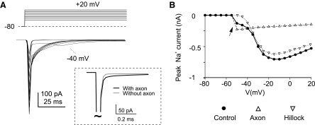
Na+ currents in the model. A: Na+ current generated in the model by stepping from −80 to 20 mV in 10-mV steps. Note the marked clamp escape around activation threshold (the −45-mV trace is indicated). Inset: the current transient elicited by a short voltage pulse injected into the soma either in the presence (black trace) or in the absence (gray trace) of the axon. The axon adds a slow component to the transient. B: I-V plots with different sodium channel distributions. The I-V plots are obtained either with control channel distribution (H/ANa = 0.5, H/AKV = 0.5, see Fig. 7), or with channels only in the hillock, or with channels only in the axon. In these panels, the simulated currents have been filtered to suit the typical response frequency of voltage-clamp recordings (−3 dB low-pass filtering at 1.6 kHz, see methods).