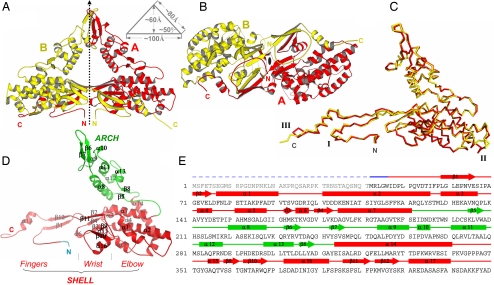
Fig. 2.
Structure of PsV-F CP. (A) Side view of the icosahedral asymmetric unit of the virus particle. The local 2f axis that relates the CPA (red) and CPB (yellow) molecules is shown. This axis is normal to the capsid shell. Dimensions of the dimer are shown in a schematic diagram. (B) CPA–CPB dimer viewed along the local 2f axis from the interior of the virus particle. (C) Superposition of CPA and CPB using all Cα atoms. The 3 most structurally divergent regions are labeled I, II, and III. (D) Structure of a CPA molecule. Secondary structure elements are labeled. (E) Secondary structure assignments in CPA. Rods, arrows, and lines represent α-helices, β-strands, and coils/turns, respectively. The disordered N-terminal region is shown by a dashed line. The color scheme follows that in D.

