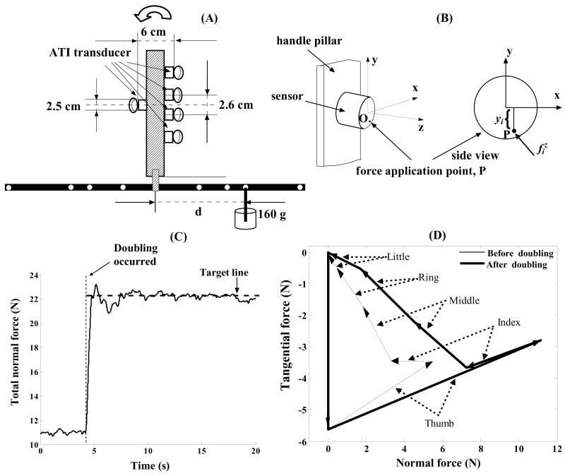
Figure 1.
The experimental apparatus and recorded forces. (A) Schematic drawing of the apparatus with five sensors mounted on a handle with a T-shaped attachment. (B) Local coordinates on each transducer. (C) Total normal force generated to match the target line after 4 seconds of natural grasping. (D) Digit force vectors recorded before and after doubling. The force polygons are obtained by adding tail-to-head the individual digit forces. Starting from the upper left corner the following forces are shown: gravity, the thumb, index, middle, ring and little finger force. Ideally, in static conditions the polygon should close. Panels (C) and (D) are representative examples, R1 task.

