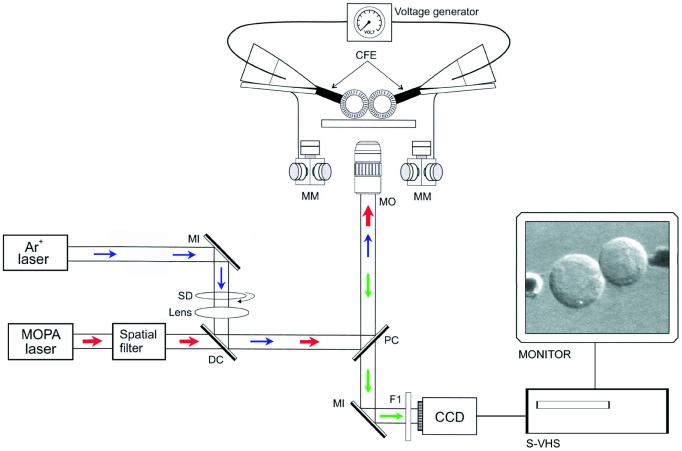
Figure 1.
A schematic drawing showing the experimental setup. Cells were added from suspension to microscope coverslips mounted in a polycarbonate holder. The cells were either prealigned by using optical trapping (MOPA laser) or simply by being pushed together with carbon-fiber electrodes (CFE) controlled by high-graduation micromanipulators (MM). The fusion pulse was applied through the CFEs (5-μm o.d.). For fluorescence imaging and optical trapping, two collinear laser beams were sent into the microscope objective (MO): (i) the 488-nm line of the argon ion laser (blue arrows) was used to excite fluorescein and FITC-labeled γ-GT, and (ii) the 992-nm output of the MOPA diode laser (red arrows) was used for optical trapping. The resulting fluorescence (green arrows) and bright-field images were directed to a CCD camera, recorded with a super-VHS video recorder (S-VHS), and continuously monitored (MONITOR). MI, mirror; DC, dichroic beamsplitter; PC, polychroic beamsplitter; F1, filter; SD, spinning disc.

