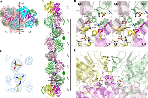
FIGURE 3.
Structure of DJ-1. A, ribbon diagram of a DJ-1 dimer in the reference orientation. IxL and IxR stand for the left and right monomers of an Ix dimer in this orientation, respectively. To distinguish monomers in the dimer, IxL is covered with transparent surface. The 2-fold axis is vertical to the figure. Green dots represent sites involved in lateral interactions, sticks represent residues implicated in the F contacts, and red spheres represent Pi. The vertical line with arrows at both ends represents the protofilament axis, that is, the rotational axis. B, ribbon drawing of a protofilament. I1–6L and I1–6R monomers are shown in pink and lime, respectively. For emphasis on the identity between I0 and I7 dimers, the two dimers are differently colored; the left and right monomers of I0 and I7 dimers are in yellow and magenta, respectively. The long line shows one longitudinal repeat unit of a protofilament. Green ellipses indicate the location of grooves involved in the lateral interactions between protofilaments, and curved green lines show the prominence regions. Pis are shown as blue spheres. The boxed region is the F interface between I0 and I1 dimers. The 2-fold axis of the F interface is vertical to the figure. C, the final 2Fo - Fc electron density map, contoured at 1 σ, showing Arg48 and an inorganic phosphate. D, front view of the boxed region of B. Residues implicated in the F contacts are labeled and represented by sticks. Oxygen, nitrogen, and sulfur atoms are shown in red, blue, and yellow, respectively. The color scheme for carbon atoms is identical to that in Fig. 1B. Polar interactions between atoms are shown as dashed white lines. E, side view of the boxed region of B. The color scheme for carbon atoms is identical to that in Fig. 1B.

