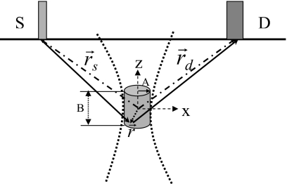
Figure 2.
A schematic for theoretical analysis. The gray cylinder represents the focal zone of the ultrasonic beam. The ultrasonic beam is indicated by two bold dotted lines. The fluorophores in the focal zone interact strongly with ultrasound wave only within the focal zone. The radius of the focal zone in x-y plane is indicated as A and the length as B in z direction. represents an arbitrary vector within the focal zone originating from origin of the coordinate system (the center of the focal zone). The two dash dotted lines with arrows indicate the positions of the light source and the detector. The two solid lines with arrows show the excitation light propagating from the source to the arbitrary position inside the focal zone and the emitted fluorescence propagating from the position to the detector.

