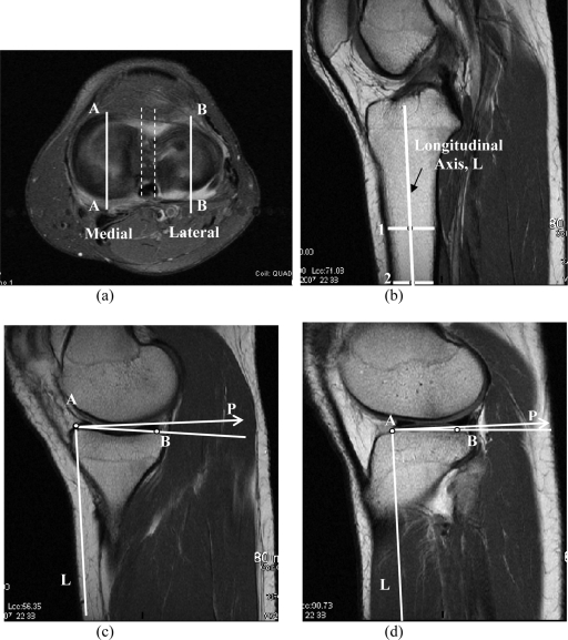
Fig. 2.
Magnetic resonance images illustrating the method used to determine the medial and lateral tibial slopes. a: The vertical lines AA and BB represent the location of the sagittal plane used for determination of the medial and lateral tibial slopes. b: The sagittal plane (represented by dashed lines in Figure 2, a) was used to determine the orientation of the diaphyseal axis in the sagittal plane. c: The axis P perpendicular to L is reconstructed on the anterior peak of the medial tibial plateau, and the medial tibial slope (represented by the slope of line AB) is measured with respect to P. d: A similar approach is used to determine the lateral tibial slope.

