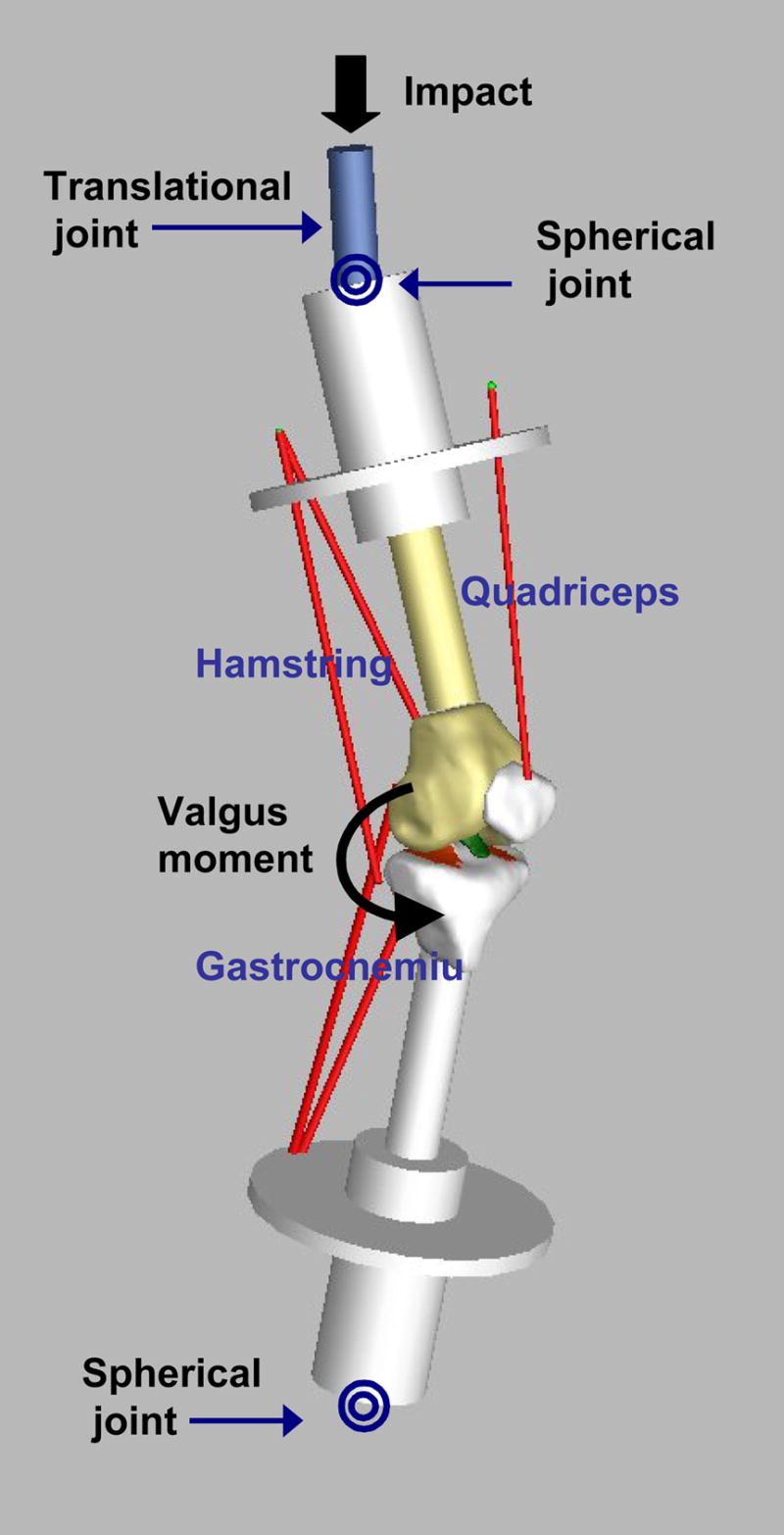
Figure 2.

An illustration of the knee model with the simulated dynamic landing apparatus showing five musculotendinous bundles (the quadriceps, the hamstrings, and the gastrocnemius). The segmented ACL is shown in green. The tibial cartilage is shown in orange. The femoral cartilage is not shown to enhance the inside view of the tibiofemoral joint. Before external loading is applied, the muscles of the knee joint are pretensioned to hold 25° of flexion. The impact force was applied at the top of the femoral axis of the upper limb and the valgus moment was applied at the tibiofemoral knee joint
