
Figure 1. Balanced amplification in the two population case.
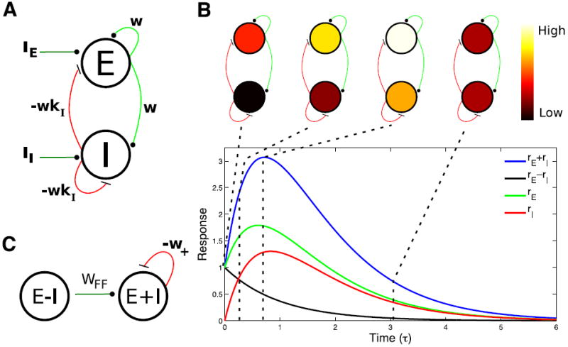
A) Diagram of a balanced circuit with an excitatory and an inhibitory population. Excitatory connections are green and inhibitory connections are red. B) Plot of the sum (blue line) and difference (black line) between activity in the excitatory (rE, green line) and inhibitory (rI, red line) populations in response to a pulse of input to the excitatory population at time 0 that sets rE (0) = 1 (rI (0) = 0). Diagrams above the plot represent the color-coded levels of activity in the excitatory and inhibitory populations at the time points indicated by the dashed lines. C) The circuit depicted in A can be thought of as equivalent to a feedforward network, connecting difference activity pattern to sum activity pattern with strength wFF = w(1+kI). In addition, the sum pattern inhibits itself with strength w+ = w(kI − 1). Parameters: kI = 1.1; (for reasons explained in Fig. 2 legend).