Fig. 3.
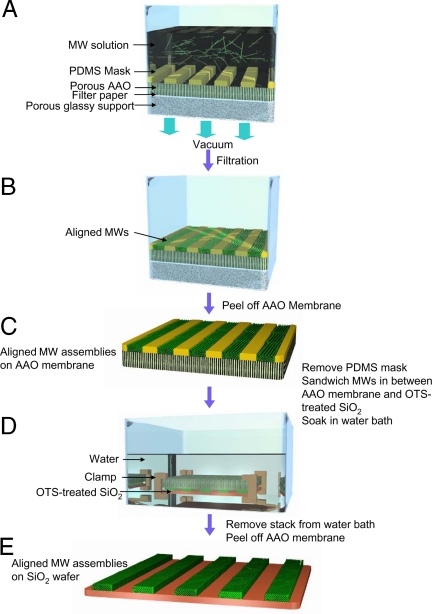
Schematic diagram for FAT alignment of organic MWs. (A) FAT alignment apparatus loaded with the MW dispersion. A PDMS mask with open-stripe patterns is placed on a porous AAO membrane. The MW dispersion is filtered by applying vacuum. (B) MW assemblies reside exclusively inside the stripe patterns of the PDMS mask after filtration. The alignment of MWs along the stripe patterns is improved substantially as the pressure difference across the filter stack is increased. The density of the aligned MWs inside a single stripe pattern can be controlled by simply changing the concentration of the MW dispersion. (C) AAO membrane covered with patterned MWs inside the PDMS mask. (D) Illustration for the transfer of the aligned MW patterns from an AAO membrane to a desired wafer substrate in aqueous medium. MWs selectively adhere to the OTS-treated SiO2 as water diffuses through the pores of the AAO membrane. (E) Aligned MWs were transferred onto the wafer.

