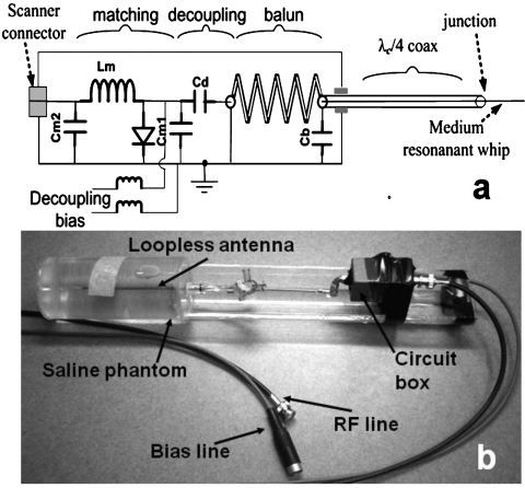
Figure 8.
(a) Schematic of the loopless antenna with its matching, decoupling and balun circuit. The balun is formed from the coaxial cable tuned with Cb and the center conductor running through to the whip: The outer conductor is grounded at the proximal end. Cd compensates for the balun inductance. (b) Annotated photograph of the 4.7 T experimental setup showing phantom, loopless antenna, and circuit box.

