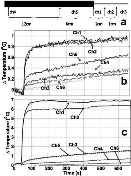
Figure 9.
Heat testing of the 3 T biocompatible nitinol loopless antenna. (a) Locations of the fiber optic temperature sensors relative to the cable (thick black section) and whip (thin line). Relative to the whip junction, Ch3 is 2 cm along the whip; Ch2 is 1 cm on the whip; Ch1 is on the junction. Ch5 and Ch4 are at 6 and 12 cm (Ch4) along the cable portion, proximal to the junction. Ch6, located remotely, serves as a control to read the phantom’s normal temperature change. (b) Temperature of the fully decoupled antenna recorded from the sensors over a 10 min period during which MRI is performed at a scanner-estimated 10 W∕kg with a higher, 0.9% saline gel to simulate a worst case heating condition. (c) With the decoupling circuit disconnected, a rapid temperature rise 7 °C is recorded in the first 100 s.

