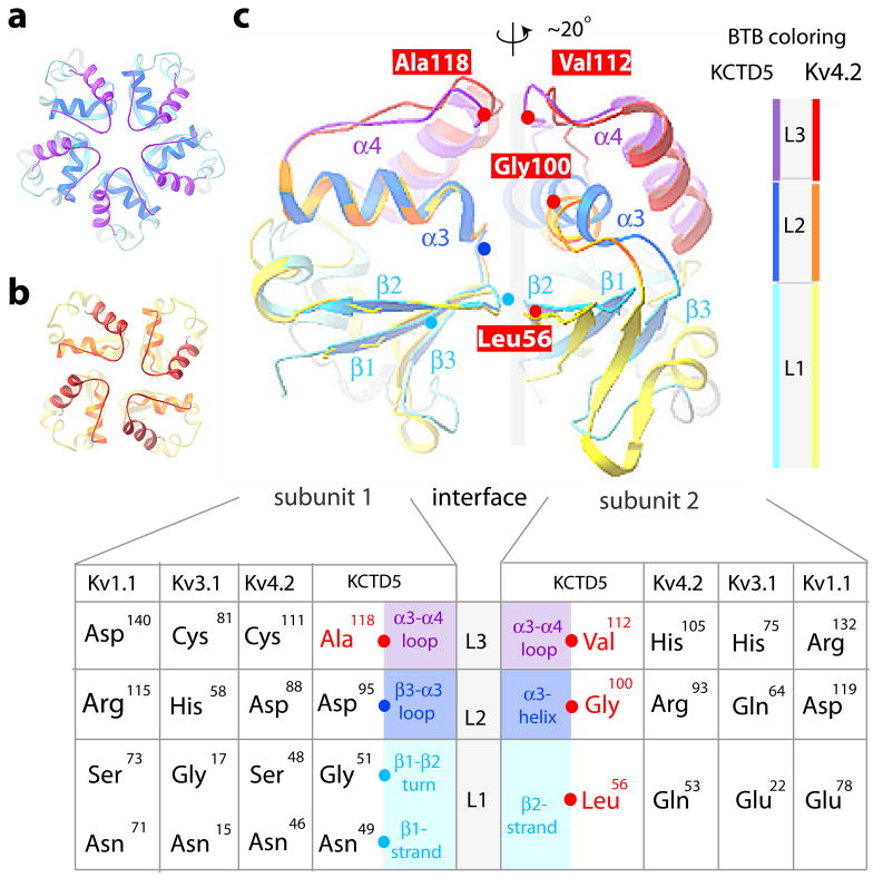
Figure 6. BTB protein-protein interfaces in KCTD5 and T1 domain assemblies.
BTB layers are: L1 in cyan (KCTD5) and yellow (Kv4.2); L2 in blue (KCTD5) and gold (Kv4.2); L3 in violet (KCTD5) and red (Kv4.2). L4 α5 helix is omitted for clarity. X-ray structures used: KCTD5 (high-salt), Kv1.1 (PDBid 1T1D), Kv3.1 (PDBid 3KVT), and Kv4.2 (PDBid 1NN7).
a. Top view of a pentameric assembly of KCTD5 N-modules.
b. Top view of a tetrameric assembly of Kv4.2 T1 domains.
c. Comparison of pairs of adjacent subunits for the KCTD5 N-module and the Kv4.2 T1 domain. To highlight the ~20° difference in orientation, subunit pairs were aligned on subunit 1 (left). Cα atoms of four key aliphatic residues in KCTD5 are noted (red spheres) and labeled; Cα atoms of their partners are in cyan (L1) or blue (L2). Inset. Correspondence of KCTD5 and T1 residues by layer with KCTD5 secondary structure elements noted. Interface H-bond pairs and distances are in Fig. S2c.

