Abstract
A user-friendly software system, UNIQUIMER 3D, was developed to design DNA structures for nanotechnology applications. It consists of 3D visualization, internal energy minimization, sequence generation and construction of motif array simulations (2D tiles and 3D lattices) functionalities. The system can be used to check structural deformation and design errors under scaled-up conditions. UNIQUIMER 3D has been tested on the design of both existing motifs (holiday junction, 4 × 4 tile, double crossover, DNA tetrahedron, DNA cube, etc.) and nonexisting motifs (soccer ball). The results demonstrated UNIQUIMER 3D's capability in designing large complex structures. We also designed a de novo sequence generation algorithm. UNIQUIMER 3D was developed for the Windows environment and is provided free of charge to the nonprofit research institutions.
INTRODUCTION
Besides its natural capability of carrying genetic information, DNA is also a remarkable design material due to its intra- and inter-molecular programmability (1,2). For more than two decades, DNA self-assembly has attracted the attentions of scientists in different research fields, such as nanotechnology, biochemistry, materials science and computer science. Building DNA objects with nanoscaled patterns or features has become a useful technique.
From the early prototypes of junction motifs (3) to a variety of structural units, such as double crossover (DX) (4), triple crossover (TX) (5), paranemic crossover (PX) (6–8), 4 × 4 tiles (9), DNA origami (10), etc., DNA motifs have become increasingly complicated. Additional design factors, such as crossover location optimization and curvature prevention must be considered to conceive sophisticated DNA motifs. It is however difficult to rely on the human imagination or physical models to design motifs. A system with 3D visualization and energy minimization is essential to design motifs design for DNA nanotechnology applications (22).
In a motif design, an algorithm must be used for de novo sequence generation for constituent DNA strands (11). Certain rules must be followed for sequence generation: the first is to follow the designed intra- and inter-molecular base pairing strategy (intramolecular base pairing is the segment complementarity of the strands within the structural motif and intermolecular base pairing is sticky end matching between motifs); the second is to make the sequences as random as possible (sequences with the lowest mismatch potential).
In our system, DNA strands can be manipulated on a 3D canvas (addition, deletion, translation, rotation, etc.). Basic DNA components can be joined together at crossover points to build certain motifs. Furthermore, geometrically unrefined motifs can then undergo energy minimization to be structurally optimized. Similar energy minimization processes can be applied to multiple motifs for array formation simulation. After the structural design is ready, sequences of DNA strands can be generated to meet the main criteria of DNA self-assembly according to the user's; specifications.
The goal of developing this system is to build a user-friendly, all-in-one program to design DNA motifs and corresponding arrays.
MATERIALS AND METHODS
System hierarchy
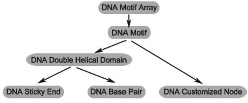
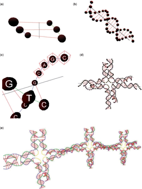
The most basic element and the lowest level of our system hierarchy is the DNA base pair. Each DNA base pair consists of a pair of nucleotide residues (DNA nodes hereinafter) connected by hydrogen bonds, and DNA nodes are rendered as spheres. Phosphodiester linkages and hydrogen bonds are rendered as lines of different colors in the 3D space. Individual nucleotide residues (DNA customized nodes hereinafter) are also modeled and rendered as spheres in our system.
The double-helical B-form DNA model is used in our system. Multiple DNA nodes can be grouped together to form a sticky end and each sticky end contains a user-defined label. Sticky ends with identical labels on different DNA strands can be joined together.
By combining several DNA double-helical domains and customized nodes, motifs can be constructed and further combined to form DNA motif arrays. The system hierarchy is shown in Figure 1 and the corresponding graphics of these components are shown in Figure 2.
Figure 1.
System hierarchy.
Figure 2.
The graphics of the structural components of different levels. (a) Three DNA base pairs. (b) A DNA double helix. (c) A sticky end. (d) A motif (4 × 4 tile). (e) A motif array.
User interface
UNIQUIMER 3D has a graphical interface for structural DNA nanotechnology (SDN) design, analysis and evaluation.
Our system allows users to design SDN models from scratch and it is able to relax a specific energy function that we define on the designed structures to predict a stable state of the structure.
At the initial stage of construction, users can add DNA double helices on a 3D canvas (x, y, z axes, each with a unit of 0.1 Å) by specifying the number of base pairs, the 3D positions and the orientations of the DNA double helices in the global coordinate system of this 3D canvas. Once the position and orientation are chosen, the rendering can be performed in the local coordinate system and then a corresponding transformation (rotation and translation associated with the given position and orientation) can be applied.
DNA customized nodes can be added in the same fashion. After DNA double helices have been added, users also have the freedom to adjust the existing structures by applying further rotations and translations in either the global coordinate system or the local coordinate system of a particular DNA double-helical domain.
A grouping operation is embedded in our system so that multiple DNA double helices with DNA customized nodes can be regrouped for further manipulation or management. The grouped components are maintained in a tree structure (a parent–child structure) that is consistent with the system hierarchy.
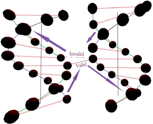
Two more operations are defined for DNA constructions: (i) the opening operation that breaks the consecutive DNA nodes; (ii) the closing operation that connects two open nodes. The two operations redefine the connectivity between DNA nodes. Invalid polarities are automatically detected by the system and will not be allowed (as illustrated in Figure 3).
Figure 3.
Valid and invalid closing operations.
Because large and complicated structures have identical or similar substructures, especially in motif arrays, copy and paste functions are desirable. In the system, when a copy operation is performed, not only is the geometric information (position and orientation of each substructure) of the selected structure copied to the clipboard, but also the configurations (structures after opening and closing operations) and the entire tree structure (representing the hierarchy), are also copied.
A certain DNA structure can be defined by specifying a set of motif arrays, motifs, DNA double helices, DNA customized nodes, sticky ends and the connectivity among them. A structural state is defined as the complete geometric information of each motif, DNA strand, DNA customized node and sticky end. A user-defined state for a complicated structure with different components is usually unstable, even after careful adjustment. To address this problem and refine the user-defined states of a structure, an energy function is designed to map each state to a nonnegative real number. This energy function reflects the stability of a structure. The lower the energy, the more stable the structure. The details of this method are presented in Energy minimization section.
UNIQUIMER 3D also has an embedded functionality for sequence generation. According to the restrictions set by users (e.g. the maximum length of repetitive segments), sequences can be assigned correspondingly to the entire structure. Details of the algorithm are presented in Sequence generation section.
UNIQUIMER 3D generates a detailed report in HTML format of the refined structure including information about its hierarchy and several showcase images of the structure from different viewing angles. The process of energy minimization is illustrated here with a chart showing each iteration in this process and the corresponding energy value.
With all these built-in features, users can easily design, analyze and evaluate different DNA structures. The energy minimization function can help users to obtain a relatively stable state of the working structure and the result can be very helpful in SDN prediction. DNA structures without satisfactory optimized states can be screened out prior to wet-lab experiments.
Energy minimization
Modeling
Given the user-defined structure (hierarchy and connectivity), a state is defined to be the entire geometric information of all of its components. An energy function is designed to assign a nonnegative real number representing its stability to each state.
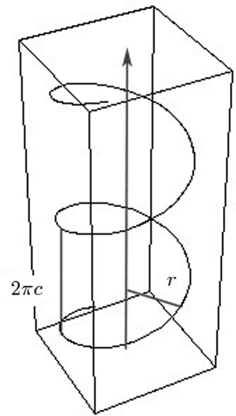
A double-helical domain is modeled as two smooth parametric curves in a local coordinate system,
 |
1 |
where t is a parameter for the two curves, r is the helix radius and 2πc is the constant that represents the vertical pitch of the helix. A segment of curve h+(t) in its local coordinate system is shown in Figure 4. We use h+ and h− to denote the helices with different polarities. Although both curves are parameterized going upward toward the positive z-axis with an increase in t in the local coordinate system, it should be pointed out that this is only for rendering convenience and does not affect any other modules in our system, such as the check for ‘valid’ and ‘invalid’ closing operations.
Figure 4.
Parametric curve h+(t) of a single helix.
Every DNA node can be addressed by the parameter t of the parametric curve of its corresponding single helix. For a DNA strand with n bases, t = {0, K, 2K, …, (n−1)K}, where K = 34.5°.
It is apparent that the curves in Equation (1) are in a local coordinate system. They can be transformed to desirable locations and orientations by applying rotation and translation, which is equivalent to multiplying the two curves by a rotation matrix and adding a translation vector.
Any rotation can be decomposed into a sequence of roll (counter clockwise rotation about the x-axis), pitch (counter clockwise rotation about the y-axis) and yaw (counter clockwise rotation about the z-axis) (12). The rotation matrix is used to represent the operation of the
 |
2 |
roll of γ first, the pitch of β second and finally the yaw of α by Equation (2).
Given a set of DNA double-helical domains,  = {D1,D2, …,Dn}, a triple, Θi = [αi, βi,γi] is associated with the roll, pitch and yaw angles, respectively. A particular double-helical domain, Di, can be rotated with Θi to a specific orientation.
The corresponding rotation matrix is then given by ℛ(Θi). Moreover, the translation vector of Di is denoted as Ti, which shifts the origin of Di's local coordinate system to Ti. Θi and Ti capture the entire geometric information of Di. After the transformation, Di has two helices with equations,
| 3 |
Furthermore, to each DNA customized node, j, a translation vector, Lj, is assigned. The translated DNA customized node will simply have location Lj after the translation.
For the current version of UNIQUIMER 3D, the B-form DNA model is rendered for all DNA structures. In fact, there are many possible conformations in addition to the most common B-form, such as A- and Z-form DNA. Besides, there are many DNA structures that are based on non-Watson–Crick B-form DNA models, such as G-quadruplexes, i-motifs and parallel duplexes. It is possible to build SDN models using other forms of DNA, like A- or Z-form DNA with similar modeling methods by changing parameters of the parametric curves and the value K. The ability to change the specifications of the DNA structure will be enabled in the next version.
Energy function
The energy function is introduced to eliminate structural defects and design errors, which might result in constructional failure, thus yielding a better evaluation of whether or not a specific DNA structure is able to form in a stable way. For random configurations of DNA strands, the energy function may be very complicated. However, a regular and predictable double-helical DNA structure makes energy minimization relatively simple. Accordingly, the distance between two nucleotide residues and the smoothness of the double helix are taken into consideration. The energy function is thus defined as
| 4 |
where Edistance and Esmoothness are two terms that are consistent with our motivation, and λ is a weight.
Since motif arrays are assembled by motifs, and motifs are further composed of DNA double helices, sticky ends and DNA customized nodes, on the basic level, only geometric information for DNA double helices, sticky ends, DNA customized nodes and the corresponding connectivity is necessary to model our energy function.
Given a set of n DNA double-helical domains and their corresponding rotation and translation parameters, Θis and Tis, and m DNA customized nodes with translation vectors, Ljs, a state can be defined as (Θ,Γ), where Θ = (Θ1, Θ2, …,Θn), Γ = (T1, T2, …,Tn, L1, L2, …, Lm).
E is a function mapping from (Θ,Γ) to nonnegative real numbers.
Edistance is defined as the sum of the squared differences of the distance between each pair of connected nodes and a constant, d. d is chosen to be the distance between any two consecutive DNA nodes on the same helix, which is 63.05. Therefore, with a user-defined connectivity map, 𝒞 = {<σ1, ρ1>,<σ2, ρ2>, …,<σk,ρk>}, where σs and ρs (s = {1,2, …,k}) denote the user-connected nodes and <· > denotes connectivity.
| 5 |
where || · || is the Euclidean norm and P(·) is a function that denotes the position of a node. It should be noted that σs (ρs) is either a node on a helix or a DNA customized node. If the node is on a helix, it will have position ℛ(Θi)· h*(t) + Ti, where Θi, t, Ti and h* = {h+, h−} depend on the working structure. If the node is a DNA customized node, j, its position is simply Lj, depending on the structure.
The second term, Esmoothness, in our energy function refines the smoothness of the user connection of the DNA double-helical domains.
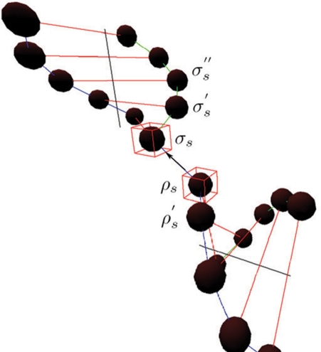
In an ideal case of DNA strand connection, the helical structures of the B-form DNA are preserved. As shown in Figure 5, two DNA double helices are joined together by connecting nodes, σs and ρs. An optimal angle between the two vectors formed by any three neighboring DNA nodes on the same helix, σs,σ′s,σ"s, is defined to be  . θoptimal is a constant that equals to 24.53. It is desirable to have a connection
  that forms the same angle, θoptimal, with both
  and
and  . Therefore, the smoothness term is defined as
 |
6 |
The summation is over all connections between nodes σs and ρs on the helices. σ′s denotes the node next to σs, which is not ρs; σ′′s denotes the node next to σ′s, which is not σs; ρ′s denotes the node next to ρs, which is not σs. This smoothness term penalizes angular discrepancies from θoptimal of the connected structure.
Figure 5.
Illustration of the smoothness term.
Optimization method
Our energy function takes (Θ,Γ) as variables. Given an initial user-defined state, (Θ,Γ), we want to improve it using an energy minimizing technique. Currently, the properties are controlled using simple geometry as defined in Edistance and Esmoothness, which is a convex function. As a result, a gradient-based local minimization algorithm is considered in this version. Powell's; method (13), which is an iterative optimization method that finds a local optimizer, is implemented in our system for this purpose.
Since the result from running Powell's; method greatly depends on its initial state, it is very important to supply a relatively stable state with low energy as the input to Powell's; method. We first coarsely scan through states that uniformly cover the solution space (Θ,Γ) to find a state with the lowest energy. Since E is a smooth function, it is reasonable to assume that a global minimum exists somewhere near this state. Therefore, this selected state is the starting point of Powell's; method.
One should note that there is no guarantee that the final state, which is a local minimum, is a global one. However, if the initial state is close enough to the global minimum, it can be found using Powell's; method.
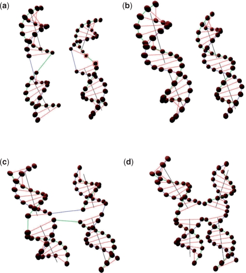
As shown in Figure 6a and c, certain DNA double-helical domains are set to be distorted. After applying energy minimization to the structures, the geometrical shapes of these double-helical domains are refined as shown in Figure 6b and d.
Figure 6.
Energy minimization. (a) Two distorted DNA double-helical domains before energy minimization. (b) Two refined DNA double-helical domains after energy minimization. (c) Two distorted DNA double-helical domains with crossover before energy minimization. (d) Two refined DNA double-helical domains with crossover after energy minimization.
Sequence generation
A number of computer software systems have been developed for DNA sequence design. SEQUIN is a FORTRAN program developed by Seeman et al. (14). It is an interactive procedure that assigns sequences for the design of SDN structures. The goal of SEQUIN is to facilitate the study of macromolecular architectures through the design of branched nucleic mono- and oligo-junctions in a convenient fashion. UNIQUIMER developed by Wei et al. (24) and TIAMAT developed by Williams et al. (15) also have this functionality with graphical interfaces for generating DNA sequences for a given DNA motif. The UNIQUIMER algorithm fills each base with A, T, G, C and a random seed is used for initialization. Whenever a segment is filled, the checkup rule is applied to the generated sequence. If there is no violation, the generation continues until all the bases are filled. Otherwise, the violated base will be canceled and selected randomly again. The method works well when the dependency of the motif structure is low. The algorithm checks the entire sequence whenever a new base sequence is randomly selected from {A, T, G, C}. Hence, it is a brute-force algorithm. More importantly, the sequence is very likely to be violated when the structure dependency is high because of the per base random selection strategy.
In order to solve this problem, a new sequence generation algorithm is designed and integrated into UNIQUIMER 3D. The new algorithm for generating sequences sacrifices storage to gain speed. The idea is to compute all the possible combinations of the specific maximum length of repetitive segment starting with {A, T, G, C}. The combination term is an unordered collection of distinct elements, usually of a prescribed size and taken from a given set. This approach guarantees that each segment is distinct in terms of sequence so that the length of repetitive segment is controlled. The combinations can be precomputed and stored into a local file that can be loaded for recycling usage.
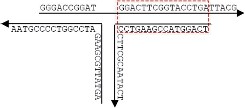
The same basic rules for SDN sequence generation are taken into consideration in UNIQUIMER 3D. The first one is the pairing up rule of {A= T}, {G ≡ C} (i.e. certain segments should be complementary, respectively, as shown in Figure 7).
Figure 7.
Base pair matching. Sequences shown in the box are subjected to complementary region.
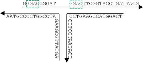
In order to avoid segment mismatching as much as possible, there is the second rule to limit the length of repetitive segments. It is illustrated in Figure 8. If the requirement is set to have no repetitive segments of 4 bp, the sequence does not meet the requirement. However, if the requirement is set to have no repetitive segments of 5 bp, the sequence will pass. As the main restriction used for sequence generation, the maximum length of repetitive segment should be set as short as possible to prevent mismatching. If the value is set to be 3, there will be no repetitive segment with a length of 4 or more bases. Suppose that we want to do sequence generation for a structure of a DNA double-helical domain with 100 bp. The total number of combinations for segments with a length of 3 bases is only 43 = 64, so if the maximum length of repetitive segment is set to be 3, there would be not enough candidates to fill in the 98 (100 − 3 + 1) blanks of segments with a length of 3 bases. Therefore, no solution could be found in this case. However, if the value is set to be 4 instead, the possible combinations increase to 44 = 256. There are enough candidates available in this case and the generator will find a solution. In general, the maximum length of repetitive segment is relatively bigger for complicated structures compared with simpler structures like DX or TX. The value ranges from 4 to 6 for most of SDN structures. However, it could be as large as 7 or more for extremely complicated structures. The maximum length of the repetitive segment in the sticky ends is set to be 3 bp (no repetitive segment of 4 bp) no matter what the global rule of repetitive segment length minimization is.
Figure 8.
Mismatching prevention. Sequences shown in the box are two repetitive segments of 4 bp.
There are also additional rules, such as customizing certain segments by defining the frequency of the segment's; appearance, excluding a certain segment of the sequence, defining the percentage of overall {G, C} and customizing the sequence of crossover point areas.
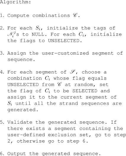
The sequence generation algorithm for UNIQUIMER 3D divides the entire structure into several partitions according to the maximum length of repetitive segment. The very first step is to find all the combinations of the user-specified maximum length of repetitive segment. The size of each combination represents the size of the distinct segments of the sequence. After all the configurations (e.g. maximum length of repetitive segment, exclusion sets, etc.) are specified, UNIQUIMER 3D will compute all the possible combinations and save the result to a file if a file corresponding to the given configuration does not exist. Otherwise, UNIQUIMER 3D will load the file of the given configuration. The combinations are stored in a 2D array containing four bins {A, T, G, C}. Each bin maintains a collection of combinations with the starting tag identical to the bin's; tag. After the combinations are computed or loaded, the sequence generator will start to assign sequences to the constructed structure. The information on DNA strands of the structure is maintained in a 1D array with the sequence assignment set to NULL. One of the combinations will be chosen at random to be the first segment of the sequence array and this combination's; state will be switched to SELECTED. At each step of generating the rest of the segments, the current segment is shifted by one base and the sequence generator refers to the combination table to mine out all the possible candidates that have not been selected. For example, if the current selected segment is [AAAT] (maximum length of repetitive segment is set to 4), the candidate list of the next segment includes [AATA, AATT, AATG, AATC] when the states of these combinations are UNSELECTED. If the current segment has been specified by the user, the generator will choose the combination according to the user's; specification, such as the crossover settings and certain segment customizations. Otherwise, it chooses the combination randomly from the possible candidate list until the entire array is filled. Eventually, the entire generated sequence is checked with additional restrictions set by users. The sequence generator will abandon the current generated sequence and regenerate a new one if such a case exists. After all the constraints are passed, the generated sequence is assigned to the constructed structure. The pseudocode of this algorithm is shown in Figure 9.
Figure 9.
Algorithm for the sequence generation.
Potential mismatching analysis
Self-assembly indicates that, if the sequence of each strand is assigned correctly, the strands will bind together to form the original designed structure. However, poor sequence assignments will lead to undesired base pairings as errors that will prevent the desired structure from forming. Two typical hybridization errors are illustrated in Figure 10. Strands 1 and 2 are originally designed to bind together according to base pairing. However, the sequences are poorly designed as the segments in the boxes can also unexpectedly bind together to form undesired structures.
Figure 10.
Hybridization errors. (a) Two segments of strand 1 bind together. (b) Two unintended segments of the strands 1 and 2 bind together.
The sequence generation functionality described in Sequence generation section limits the number of mismatching cases in the generation phase. In the analysis phase, UNIQUIMER 3D can calculate the number of potential mismatching cases that are hindrances to the formation of the desired structure. Given the length of potential mismatching segment, a scoring system of a generated sequence for a structure is formulated as follows:
Pair is defined as
Comp is defined as
 = {D1, D2, …, Dn} is the set of DNA double-helical domains, Di ∈
  is a particular double-helical domain with |Di| base pairs
 . In each doublet,
  represents the complementary base of 𝒩ji. Given the digit d that represents the length of potential mismatched segment, a score function is defined as
 |
The score function, J, is a numerical representation of the expected formation of the structure consisting of a set of DNA double-helical domains  . In a real self-assembly process, potential mismatched cases will result in formation of undesired structures.
  = {S1, S2, …,Sn} is the set of DNA strands, Si ∈
  is a particular strand with |Si| bases {𝒩i1, 𝒩2i, …,𝒩|Si|i}. We then define another score function, Ĵ, taking into account all potential mismatching cases as a comparison with the value we get from J. Since J is the most optimal score, Ĵ is always greater than or equal to J. The difference between these Ĵ and J indicates how likely the strands
  with generated sequences will self-assemble into the expected structure. The smaller the difference between the values we get from Ĵ and J, the more likely
  will self-assemble into the expected structure formation.
 |
Ĵ is designed to find all potential mismatched cases, which is equivalent to string matching. The algorithm searches for the reversed complements of a given set of segments based on DNA base pairing {A=T}, {G≡C}, {T=A}, {C≡G}. Consider segment  as the template, it is equivalent to essentially searching on strand j for the total number of reversed complements. As a result, the Boyer-Moore (16) string search algorithm is adopted for Ĵ.
Our score functions take a structure with a sequence and the length of the potential mismatched segment, d, as input. A set of sequences generated n times of a structure is denoted as Φ = {Φ1, Φ2, …, Φn}. The corresponding numbers of potential mismatched cases are denoted as  . A tuple Δd = [Ω, Φ] is associated. Ωi = min(Ω), Δdi = [Ωi, Φi] is selected for a specific d.
RESULTS
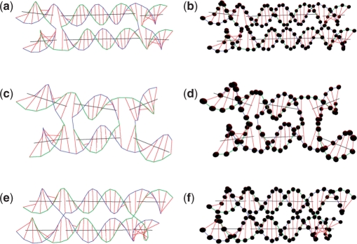
Some existing motifs including two types of DX (DAE and DPON) (17), a tetrahedron and a cube are constructed using UNIQUIMER 3D. The weight, λ, of these structures was set to 0.5. In Figure 11, the DX are set to be parallel to each other as the initial state. A DAE model that is antiparallel with two half-turns (21 bp) between crossovers is shown in Figure 11a and b. After energy minimization (the two duplex axes rotate about 3° relative to each other. Similarly, a DAE model with one half turn (10 bp) between crossovers is shown in Figure 11c and d. The two duplex axes rotate about 20° after energy minimization. The case of the DPON model, which is parallel with around 1.5 turns (16 bp) between crossovers, is shown in Figure 11e and f. Two duplex axes have around 0° of rotation relative to each other after energy minimization.
Figure 11.
DX motifs. (a) DAE structure (21 bp between crossovers). (b) DAE structure with DNA nodes rendered (21 bp between crossovers). (c) DAE structure (10 bp between crossovers). (d) DAE structure with DNA nodes rendered (10 bp between crossovers). (e) DPON structure (16 bp between crossovers). (f) DPON structure with DNA nodes rendered (16 bp between crossovers).
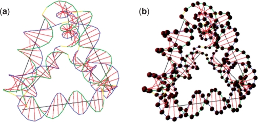
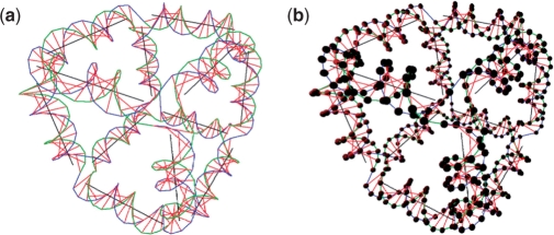
The tetrahedron (18) with an edge length to be 21 bp, constructed using four DNA strands, is shown in Figure 12 and the cube (19) constructed using six DNA strands is shown in Figure 13. After energy minimization, the original shapes are slightly distorted from the ideal symmetric shapes.
Figure 12.
Tetrahedron structure. (a) Structure without DNA nodes rendered. (b) Structure with DNA nodes rendered.
Figure 13.
Cube structure. (a) Structure without DNA nodes rendered. (b) Structure with DNA nodes rendered.
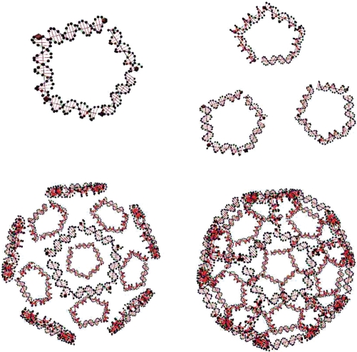
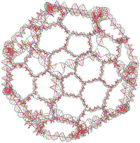
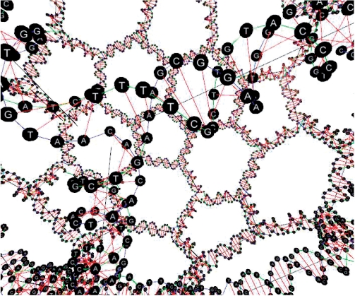
A nonexisting motif that we call a soccer ball is constructed using UNIQUIMER 3D as well. Topologically, it consists of 20 hexagons and 12 pentagons. The structure is constructed using 32 DNA strands. Twenty strands of 126 bases long while the other 12 strands have 105 bases. The stepwise design of a soccer ball structure is shown in Figure 14, and the overview of the soccer ball after energy minimization is shown in Figures 15 and 16. We have demonstrated UNIQUIMER 3D's; capabilities of designing, analyzing and evaluating complex structures in a 3D environment in a user-friendly fashion.
Figure 14.
The stepwise design of a soccer ball structure.
Figure 15.
Soccer ball structure rendered without sequence generation.
Figure 16.
Soccer ball structure rendered with sequence generation.
The sequences generated by our system for the DNA tetrahedron and the DNA cube are shown in Tables 1 and 2, respectively. In the sequence generation process, the maximum length of repetitive segment of the sequence is set to be five. The sequence generated by our system for the soccer ball motif is shown in Table 3, and the maximum length of repetitive segment of the sequence is set to be seven.
Table 1.
Sequence of the DNA tetrahedron
| DNA strand | Sequence |
|---|---|
| 1 | GTCCCTGCGGTCTTGGTAGGTACTTGCTATGTCCGTCCATGTTTTGGGAACGAGAGTCACCGT |
| 2 | CTAAAACCTGGGGAGTGTATTGTGAAGTTAGGCCTTGAGTAGATGCCTACCAAGACCGCAGGG |
| 3 | TTATCTACTCAAGGCCTAACTTTCCCCTTTTTGCCCGAATTTTTACATGGACGGACATAGCAA |
| 4 | ATAAAAATTCGGGCAAAAAGGGTGCAATACACTCCCCAGGTTTTTCGGTGACTCTCGTTCCCA |
Table 2.
Sequence of the DNA cube
| DNA strand | Sequence |
|---|---|
| 1 | CTTAGGCCCTTGGACTCGACAGGCGCTCTAAGATCCCTCGTCAGAGTCCATGTGGCCTCTCGCCCAGCGATGAGGTTAGT |
| 2 | GAAAACGTGTAGGAAGGCTAATACATACCTCCTATGCTTTGGTAGCTCAATTACCAAAGGGGTCGAGTCCAAGGGCCTAA |
| 3 | TCCCTTTGGTAATTGAGCTACCCCGCTTGACTACGCGGCGTCCCATAGAATGATCGCATTACGAGGGATCTTAGAGCGCC |
| 4 | ATAATGCGATCATTCTATGGGTGTCAAGTTTACGGTCCTGGCACGAGCCGGTTCGAATATTAGAGGCCACATGGACTCTG |
| 5 | GAATATTCGAACCGGCTCGTGAGAACATTGTCGATAGGTGCTTAGCCTTCCTACACGTTTTACTAACCTCATCGCTGGGC |
| 6 | AGCACCTATCGACAATGTTCTCCAGGACCGTAAACTTGACAACGCCGCGTAGTCAAGCGGGCAAAGCATAGGAGGTATGT |
Table 3.
Sequence of the soccer ball
| DNA strand | Sequence |
|---|---|
| 1 | GAGATTAGTTGGCTACTGCTGTCTCAATGTGCGGCATCCCTAAGGTCTGAGCGGATTAGAGCAACGCTCCACCATTTCGATAGTAGCGTTATGCGTAATCCGCAA |
| 2 | CAAAAAAACCCGTTCGAAAGATAGTCTCACGTATAAACCTAATCACGCGATTAGGAATAGGCTCCATGCATTGACTCTGGTAAATTGGCCGTACATAAACAGGGAGCAGCAGTAGCCAACTAATCT |
| 3 | ACTCCCTGTTTATGTACGGCCAAAGGCAGGATATTATAAGGCATGTGAACTAAAAATCACAAGGGAGGGCGAACAGTCTCCTGGAATGAATTTCTCTAGTGGCCGATAGGGATGCCGCACATTGAG |
| 4 | TTCGGCCACTAGAGAAATTCATTGTTGGTTCAGCTTCTCGTCGGGGTTTCCAACGTGATTGCTGAAAGCGGAACATGGGACCCGCCATATTGGCGAAACCGGTTCTTGCTCTAATCCGCTCAGACC |
| 5 | TAGAACCGGTTTCGCCAATATGTAAATGAGCGTGGTCTCCCTCCAATGTCTAGCGTGTCATAGGATTGACGCCATTCGCCGCTGGGTGTAAAAAGAGATGTGACTTACTATCGAAATGGTGGAGCG |
| 6 | TAAGTCACATCTCTTTTTACACGGTCTAAGGCCGGCTCCTGAAATCTACTGTTATGGCGCAGCACCAGCATGAGGACTGACTGATATCTTTCGAACGGGTTTTTTTTTGCGGATTACGCATAACGC |
| 7 | CCCAGCGGCGAATGGCGTCAATTAGGGCAAGTTAAATCCGGACCGGACGCGAGCCACTGCTCTCCACACTCTTACATTGTATACGTTCAGGAGCCGGCCTTAGAC |
| 8 | CGTATACAATGTAAGAGTGTGTAACCCCACACGTGTTTGGCGGTGAACAAGACTGTTCGCACCCACGTTCCGTACTAGGGTCGGGCGGGAAGGCGCGGCCTCATATGCTGCGCCATAACAGTAGAT |
| 9 | GAGAGCAGTGGCTCGCGTCCGTCTCTATAAGCTCATAGCATCAAGGACTAAGCTAAAAGGCGGACGAGGGAGTCCTAACAAGCGGTACTCGCCTTCAGTGACGAGCGCCAAACACGTGTGGGGTTA |
| 10 | GTCCGGATTTAACTTGCCCTACCTATGACACGCTAGACATTGCTATGGCCATACGTCACCAGACCTAACTAACTTTGAGGAAAGTTCAATGAGAGCGTTGGGCCGGATGCTATGAGCTTATAGAGA |
| 11 | TACTACCTCTGCGACTATCCTCTTAGAGGACGGTGGGCAGATCTGGTGACGTATGGCCATAGGAGGGAGACCACGCTCATTTAGCGGGTCCCATGTTCCGCTTTT |
| 12 | AGTTCGTTACGGGGAGGTGCTCAGTATATCAGTAGTCCCGCGACCACAGAGGTCGTTCATTCGGATAGTCGCAGAGGTAGTAACAGCAATCACGTTGGAAACCCTGTATTCGGGGATGTTGCACGG |
| 13 | AGAATGAACGACCTCTGTGGTCCTTGGCAATACTCTGCACGTCTCCGGAGCCAGACAACGGGGTACTTCAGGGCTGCACTAGGTGCTTTCCTCAAAGTTAGTTAGGTCTGCCCACCGTCCTCTAAG |
| 14 | ACACCTAGTGCAGCCCTGAAGTACGTCGCGCGTGGGGACGAAGTTTCTCGCTGTGACGGGGGGACCGCCTTTTAGCTTAGTCCTTCGGCCCAACGCTCTCATTGA |
| 15 | CCCCCCGTCACAGCGAGAAAGTGCCAGCACTTGTACTTAAGTAAAATACAACGCGTCGTCTCGATGAGTGGATACGCGCGCTACTTTTATGGACTCGGCTTGATCGCTTGTTAGGACTCCCTCGTT |
| 16 | CTTCGTCCCCACGCGCGACGTACCCCGTTGTCTGGCTCCGGAACCGCGTCTACTCTAGGTAGAACATCAATATTTGGTCGAAGTGCGAGTGACCGGCGGGGACTGCTTAAGTACAAGTGCTGGCAC |
| 17 | GACGTGCAGAGTATTGCCAAGGCGGGACTACTGATATACTGAGTTCGACTCCAAGAGTTCTTCAACGGTGTGTGGACATAGACCTCTACCTAGAGTAGACGCGGT |
| 18 | CGCACCTCCCCGTAACGAACTCTGTCGTGACATGATGCTGTGCGATTGGAACTATCTGTCCTGCGGACTGGGATGGTTCGGTATCCACAGCATATGGGTGGAAATCGAAGAACTCTTGGAGTCGAA |
| 19 | TGATTTCCACCCATATGCTGTGGATTTCTATTATGTCAACTACGTACACCAAGACATCCGTGGTGATGAAATTACCTGGGGTAGAACTTCGACCAAATATTGATGTGGTCTATGTCCACACACCGT |
| 20 | AGAGACGACGCGTTGTATTTTACAGTCCCCGCCGGTCACTCGCTCTACCCCAGGTAATTTCATCAACTCTATGCAAGCTTCAGCGTAAATAGATTGCACTTCGGA |
| 21 | TTCCGAAGTGCAATCTATTTACCCGCAGAAGAAAGGCCAGGGTAGCATGCCATGTGGCCTTCTCTCAAAATTGCATCCTTCTGGTCAGCAGGTCGCCCCCCACCCTAGCGCGCGTATCCACTCATC |
| 22 | CGCTGAAGCTTGCATAGAGTTACCACGGATGTCTTGGTGTACCTTCTTCCTCTCAGCTGACATATATGCGCAAAGTACCTGTTCCTGGTTCTCGGATTCGGTTGTCCCTGGCCTTTCTTCTGCGGG |
| 23 | CAAAAAATTCGTATTTGATTTTCCAGCCTGTAACTGCTAGTACATGTCAGCTGAGAGGAAGAAGGTAGTTGACATAATAGAAATCGATACCGAACCATCCCAGTC |
| 24 | TGCAGGACAGATAGTTCCAATCCTAGGGGATCCGCGAACCCGGCCTTGTGATTTTTAGTTCACATGGAAGTATAGAATTCGCTTAGGTAAAAGCACGGCTGTAATGAAAATCAAATACGAATTTTT |
| 25 | GCATTACAGCCGTGCTTTTACCTTGTATGGGGCGTTTGTAAGCTGATCTTGGCCTAACGTGCCGTATCGCAGGCTCTCGTTGCGTGAACAGGTACTTTGCGCATATGTACTAGCAGTTACAGGCTG |
| 26 | GACGCAACGAGAGCCTGCGATACTAGATCAGACGTAATATGGTTAGTGTACTGTCATGGGGGTAAGAAGGCCACATGGCATGCTAACAACCGAATCCGAGAACCA |
| 27 | TACCCCCATGACAGTACACTACGAAGCTCCAGGACGCTTATCGACCCGGTTACGCTACCGAGCCCGACCCTAGTACGGAACGTGGTATATTAGGCTTGCGTTAATCCAGAAGGATGCAATTTTGAG |
| 28 | ACCATATTACGTCTGATCTAGCGGCACGTTAGGCCAAGATCACTTAAAATCTTAGCCGTCAGTGAGCCTATTCCTAATCGCGTGTTCATGTCGAGGCAGAACACGGATAAGCGTCCTGGAGCTTCG |
| 29 | GCTTACAAACGCCCCATACAATAAGCGAATTCTATACTTCCATGCCTTATAATATCCTGCCTTATTTACCAGAGTCAATGCATGACTGACGGCTAAGATTTTAAG |
| 30 | ATTAGGTTTATACGTGAGACTATCAGTCAGTCCTCATGCTGGTATGAGGCCGCGCCTTCCCGCGCTCGGTAGCGTAACCGGGTCCGTGTTCTGCCTCGACATGAA |
| 31 | AATTAACGCAAGCCTAATATACGGTGCGAACAGTCTTGTTCACCTCGTCACTGAAGGCGAGTACATCAAGCCGAGTCCATAAAAGGGGTGGGGGGCGACCTGCTG |
| 32 | CCGGGTTCGCGGATCCCCTAGGCACAGCATCATGTCACGACACGTGCAACATCCCCGAATACACGACGAGAAGCTGAACCAACATCCAGGAGACTGTTCGCCCTC |
DISCUSSION
Related work
SDN design in the 3D environment has generated a lot of interest recently.
NAMOT (20) and NAMOT2 (21) were developed by Tung and Carter in the mid-1990s. They are graphic tools to build and manipulate nucleic acid structures. However, most of the efforts have focused on animation and visualization. Users need to adjust individual geometrical structures one by one. In such cases, these 3D systems cannot scale to support large numbers of DNA elements. The user's; experience will be rather poor if the structure with high dependencies is complex.
GIDEON (22) was developed by Jeffrey in 2006 to provide a user-friendly graphical interface that allows construction and viewing of complex SDN models with ideal precision. Unlike NAMOT, GIDEON is equipped with a rudimentary relaxation algorithm that can help fit the elements of a construction together in a smooth and low-strain configuration and can be used to get qualitative estimates of the strain expected for a given design. Its major approach is iterative calculation of vectors as a function of each segment's; orientation and translation of the segment endpoints. The vectors shorten or lengthen each segment to reduce the error defined as the segment's; current length relative to its target length. A similar approach is used to minimize the planar and torsional angular strains.
Our work is different from pure graphical visualization tools in the following respects. First, unlike traditional visualization software, the editing environment is rendered in real time so that users have a 3D walk through experience while designing their structures. Second, if the dependency of the structure is high and users find it extremely difficult to adjust the structure to a stable state with low internal geometrical energy, UNIQUIMER 3D has an energy minimization utility that can adjust the designed prototype to a relatively stable state. On the other hand, if the design of the structure is a failure and it can never be adjusted to a stable state, UNIQUIMER 3D is able to suggest modifications to the original structure. Although GIDEON is also equipped with similar functions, our energy minimization algorithm has the following strengths. First, by using energy functions, it is flexible in adding or reducing terms of the energy function. Second, when the motif array is large, it is time consuming to calculate the relaxation vectors for each connected component as done by GIDEON. Our energy minimization algorithm is able to find the stable state of the user-defined structure for all the connected components at each iteration so that the time complexity is greatly reduced. In addition, we integrated a sequence generation algorithm into our program. It is capable of generating a sequence of a given structure randomly following the pairing up and mismatching prevention rules.
There are also nucleic acid computation programs for the design of RNA structures, which have many analogies with SDN designs. NanoTiler aimed at automated design of RNA nanostructures developed by Bindewald et al. (23), is a representative program. The systems designed for RNA structural design are inspiring for DNA nanotechnology design. The algorithms developed for each application can be shared to enrich each other.
Conclusion and future work
In this article, we presented a novel, user-friendly system with a graphical interface, UNIQUIMER 3D, for DNA nanotechnology design, analysis and evaluation. The main contributions of this work are summarized as follows:
Users can visualize DNA motifs and motif assemblies in a 3D environment.
Users can design DNA structures in a convenient and efficient way.
An energy function is designed for measuring the stability of structures. Our system can relax this energy function to predict a relatively stable structure, which can validate and/or predict SDN wet-lab experiments.
Each DNA node in a structure can be automatically assigned a tag from {A, T, G, C} using a built-in sequence-generating algorithm, and the generated sequence can be analyzed by our scoring system.
A detailed HTML report is generated after the energy minimization, which contains hierarchical information on the refined structure, showcases images of it from different viewing angles and gives information on the energy minimization.
In our future development, we will work on the 3D modeling down to the molecular level with precise atomic positional control, so that the energy function will be directly related to the chemical bond rotation of the DNA backbone structure. Besides, DNA of different conformations (e.g. A-DNA, Z-DNA) or even RNA will be modeled in the system. Hopefully, PDB format, which is a popular format for 3D structures of proteins and nucleic acids, can be supported by them. We will also work on the structural optimization and sequence optimization to get the designed structures more likely to form. For the structure aspect, a systematic analysis of the energy minimization will be carried out to the molecular level of DNA backbone structures. Instead, the current single-level algorithm with low efficiency for energy minimization process, multi-level optimization that can minimize all factors simultaneously at each iteration will be utilized to increase the efficiency of the process. In addition, the simulated annealing method that can sample a wider range of conformations compared with other gradient-based local minimization methods will be considered to get better chances to find the most stable structures. For the sequence aspect on the other hand, we are going to add more analysis function to make sure the sequence generated is likely for the desired structure but not the undesired structure from mismatching. At the current stage, only continuous segments of mismatching are taken into consideration. It will be more appealing to apply the undesired secondary structure prevention to the discontinuous segments as well so as to get a better picture of the overall possibilities of the formation of undesired secondary structure. We shall try to include both continuous and discontinuous in the scoring function in the next version of the system. An even more ambitious plan is a wet-lab simulation. To be specific, given enough modeling information and rules, the generated sequences can be put back to the system and let the system figure out the possible structure formation. Then, we can compare the simulation result with the projected structure of a design to see whether the design in a whole is a sound one.
Funding
Hong Kong RGC (604606) for construction of DNA 3D superstructures by DNA self-assembly, through the earmarked grant from the University Grants Council of the Hong Kong government. Funding for open access charge: University Grants Council of the Hong Kong government, RGC 604606 and RGC 602405.
Conflict of interest statement. None declared.
Footnotes
UNIQUIMER 3D software can be requested by e-mailing the corresponding author or through http://ihome.ust.hk/~keymix/.
REFERENCES
- 1.Seeman NC. DNA in a material world. Nature. 2003;421:427–431. doi: 10.1038/nature01406. [DOI] [PubMed] [Google Scholar]
- 2.Seeman NC. DNA engineering and its application to nanotechnology. Trends Biotechnol. 1999;17:437–442. doi: 10.1016/s0167-7799(99)01360-8. [DOI] [PubMed] [Google Scholar]
- 3.Kallenbach NR, Ma RI, Seeman NC. An immobile nucleic acid junction constructed from oligonucleotides. Nature. 1983;305:829–831. [Google Scholar]
- 4.Li X, Yang X, Qi J, Seeman NC. Antiparallel DNA double crossover molecules as components for nanoconstruction. J. Am. Chem. Soc. 1996;118:6131–6140. [Google Scholar]
- 5.LaBean TH, Yan H, Kopatsch J, Liu F, Winfree E, Reif JH, Seeman NC. Construction, analysis, ligation, and self-assembly of DNA triple crossover complexes. J. Am. Chem. Soc. 2000;122:1848–1860. [Google Scholar]
- 6.Seeman NC. DNA nicks and nodes and nanotechnology. Nano Lett. 2001;1:22–26. [Google Scholar]
- 7.Zhang X, Yan H, Shen Z, Seeman NC. A robust DNA mechanical device controlled by hybridization topology. J. Am. Chem. Soc. 2002;124:12940–12941. doi: 10.1038/415062a. [DOI] [PubMed] [Google Scholar]
- 8.Shen Z, Yan H, Wang T, Seeman NC. Paranemic crossover DNA: a generalized Holliday structure with applications in nanotechnology. J. Am. Chem. Soc. 2004;126:1666–1674. doi: 10.1021/ja038381e. [DOI] [PMC free article] [PubMed] [Google Scholar]
- 9.Yan H, Park SH, Finkelstein G, Reif JH, LaBean TH. DNA-templated self-assembly of protein arrays and highly conductive nanowires. Science. 2003;301:1882–1884. doi: 10.1126/science.1089389. [DOI] [PubMed] [Google Scholar]
- 10.Rothemund PWK. Folding DNA to create nanoscale shapes and patterns. Nature. 2006;440:297–302. doi: 10.1038/nature04586. [DOI] [PubMed] [Google Scholar]
- 11.Seeman NC. De novo design of sequences for nucleic acid structural engineering. J. Biomol. Struct. Dyn. 1990;8:573–581. doi: 10.1080/07391102.1990.10507829. [DOI] [PubMed] [Google Scholar]
- 12.Buss SR. 3D Computer Graphics: A Mathematical Introduction with OpenGL. Cambridge, England: Cambridge University Press; 2003. [Google Scholar]
- 13.Powell MJD. A fast algorithm for nonlinearly constrained optimization calculations. Proc. Numer. Anal. 1977;630:144–157. [Google Scholar]
- 14.Seeman NC. De novo design of sequences for nucleic acid structural engineering. J. Biomol. Struct. Dyn. 1990;8:573–581. doi: 10.1080/07391102.1990.10507829. [DOI] [PubMed] [Google Scholar]
- 15.Williams S, Lund K, Lin C, Wonka P, Lindsay S, Yan H. Tiamat: a three-dimensional editing tool for complex DNA structures. In: Goel A, Simmel FC, Sosík P, editors. The 14th International Meeting on DNA Computing Proceedings. Czech Republic: Silesian University in Opava; 2008. pp. 112–121. [Google Scholar]
- 16.Boyer RS, Moore JS. A fast string searching algorithm. Commun. ACM 20. 1977;10:762–772. [Google Scholar]
- 17.Fu T-J, Seeman NC. DNA double-crossover molecules. Biochemistry. 1993;32:3211–3220. doi: 10.1021/bi00064a003. [DOI] [PubMed] [Google Scholar]
- 18.Goodman RP, Berry RM, Turberfield AJ. The single-step synthesis of a DNA tetrahedron. Chem. Commun. 2004;12:1372–1373. doi: 10.1039/b402293a. [DOI] [PubMed] [Google Scholar]
- 19.Chen J, Seeman NC. Synthesis from DNA of a molecule with the connectivity of a cube. Nature. 1991;350:631–633. doi: 10.1038/350631a0. [DOI] [PubMed] [Google Scholar]
- 20.Tung C-S, Carter II ES. Nucleic acid modeling tool (NAMOT): an interactive graphic tool for modeling nucleic acid structures. Comput. Appls. Biosci. 1994;10:427–433. doi: 10.1093/bioinformatics/10.4.427. [DOI] [PubMed] [Google Scholar]
- 21.Carter ES, Tung C-S. NAMOT2-a redesigned nucleic acid modeling tool: construction of non-canonical DNA structures. Comput. Apps. Biosci. 1996;12:25–30. doi: 10.1093/bioinformatics/12.1.25. [DOI] [PubMed] [Google Scholar]
- 22.Birac JJ, Sherman WB, Kopatsch J, Constantinou PE, Seeman NC. Architecture with GIDEON, a program for design in structural DNA nanotechnology. J. Mol. Graph. Model. 2006;25:470–480. doi: 10.1016/j.jmgm.2006.03.005. [DOI] [PMC free article] [PubMed] [Google Scholar]
- 23.Bindewald E, Grunewald C, Boyle B, O'C;onnor M, Shapiro BA. Computational strategies for the automated design of RNA nanoscale structures from building blocks using NanoTiler. J. Mol. Graph. Model. 2008;27:299–308. doi: 10.1016/j.jmgm.2008.05.004. [DOI] [PMC free article] [PubMed] [Google Scholar]
- 24.Wei B, Wang Z, Mi Y. Uniquimer: software of de novo DNA sequence generation for DNA self-assembly-an introduction and the related applications in DNA self-assembly. J. Comput. Theor. Nanosci. 2007;4:133–146. [Google Scholar]


