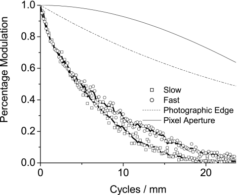
Figure 13.
The modulation transfer function (MTF) of the scanner is shown in both the fast scan and slow scan directions. In each direction both averaged data and data created by the condition that the ESF be monotonically increasing are included; the data are corrected for the imperfect MTF of the photographic edge. For comparison, the MTF of a sinc function and the photographic edge used in measurement are shown.

