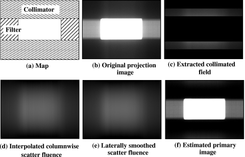
Figure 3.
Scatter correction procedure is illustrated with example images. (a) The collimators and the IW filters are positioned. (b) Original projection image of a phantom. (c) Projection data under the collimators are extracted. (d) Column wise interpolation is applied for each column. (e) Lateral smoothing is performed to finally estimate the scatter fluence. (f) Original image subtracted by the estimated scatter fluence.

