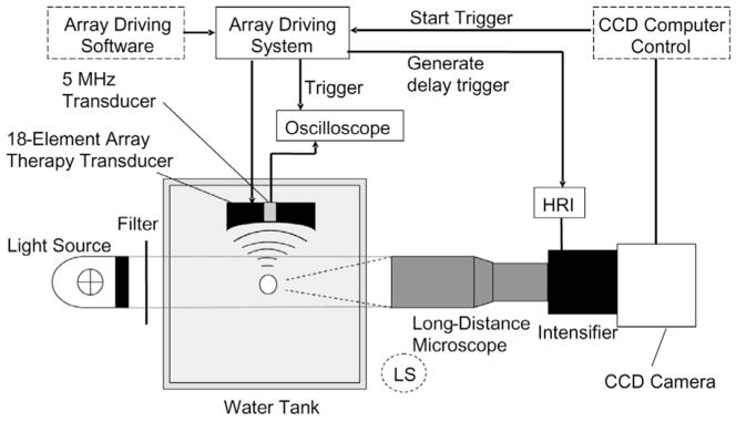
Fig. 1.
Schematic drawing of experimental setup for high speed imaging and acoustic backscatter recording. The light source position shown was for bubble shadowgraph acquisition. For whole bubble cloud imaging with forward lighting, the long-distance microscope was replaced by lenses described in the methods section and the light source was moved to the position labeled as “LS” (dashed circle).

