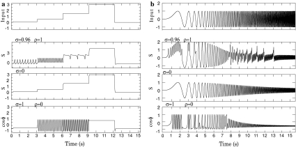
Fig. 4.
Voltage response to input currents. a for current steps, b for oscillatory input of increasing frequency. Upper figures show the input pattern. Then, from up to down, the voltage response is shown for our complex unit, then for a unit without phase modulation, finally, when only the phasic output is considered

