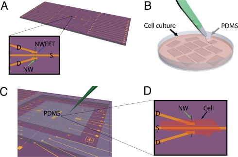
Fig. 1.
Schematic of the experimental approach. (A) NWFET chip, where NW devices are located at central region of chip. The visible linear features (gold) correspond to NW contacts and interconnect metal. Zoom-in showing a source (S) and 2 drain electrodes (D) connected to a vertically oriented NW (green arrow) defining 2 NWFETs. (B) Cardiomyocytes cultured on thin rectangular pieces of PDMS, where the black arrow highlights 1 piece in the culture medium, and the gray arrow indicates 1 piece being removed with tweezers (green). (C) PDMS piece with cultured cells oriented over the device region of NWFET chip. The green needle-like structure indicates the probe used to both manipulate the PDMS/cell substrate to specific NW device locations and to apply local force to the NWFET/cell junction. (D) Schematic view of a cardiomyocyte (black arrow) oriented over a NW (green arrow) FET device.

