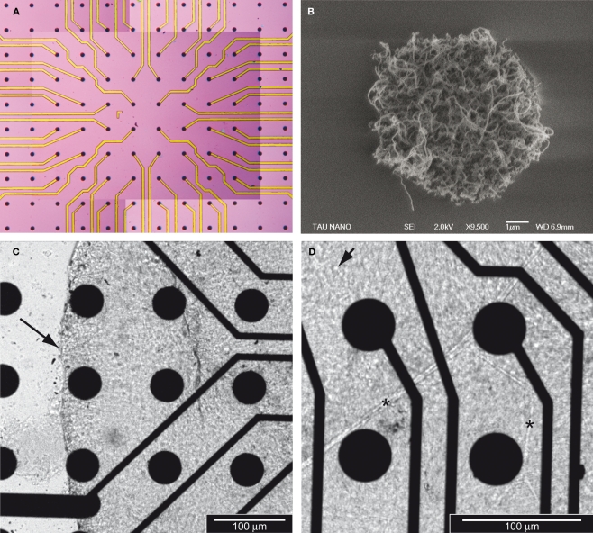
Figure 1.
Carbon nanotube MEAs for retinal interfacing and recording. (A) General view of a CNT MEA. Each black dot is a CNT island. All 60 islands in the center of the field are electrodes whilst those at the periphery are not. (B) Micrograph of one CNT island (9,500× magnification) revealing the porous nature of the CNTs. Note that the island in Figure 1B is a smaller island than those used in the CNT MEA configuration. (C) Micrograph (20× magnification) of a retina laid on a CNT MEA. The retina is flattened on the CNTs, with the RGC layer facing down, hence in contact with the CNTs. The arrow indicates the edge of the tissue. (D) Micrograph (32× magnification) of the same retina as in (C). The arrow points to a RGC body and the asterisks to blood vessels.

