FIGURE 1.
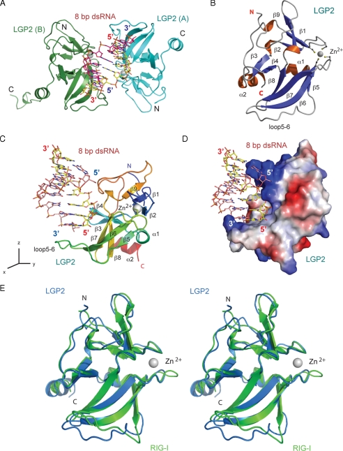
Structure of human LGP2 C-terminal domain in complex with an 8-bp dsRNA. A, two LGP2 CTD bound to the termini of an 8-bp blunt-ended dsRNA in the crystallographic asymmetric unit. The two protein molecules are shown as cyan (LGP2, A) and green (LGP2, B) ribbons. The dsRNA is shown as a stick model. The zinc ions in LGP2 CTD are shown as gray spheres. B, ribbon representation of the structure of LGP2 CTD. The dsRNA-binding surface of LGP2 is defined by the β-sheet containing β5 to β8, the loop connecting β5 to β6 (loop5-6), the hairpin containing β3 and β4, and the two loops connecting β5 to β6, and β9 to the C-terminal helix. The side chains of the four conserved cysteine residues coordinating with the zinc ion are shown as stick models. C, structure of LGP2 CTD bound to the 8-bp dsRNA. LGP2 CTD is colored as a rainbow from blue at the N terminus to red at the C terminus. The orientation of LGP2 is related to that of LGP2 in B by a rotation of ∼90° counter-clockwise along the z axis. D, electrostatic surface potential (ranging from blue = 10 kT/e to red = -10 kT/e) of LGP2 CTD showing the high degree of shape and charge complementarity between LGP2 CTD and the first turn of blunt-ended dsRNA. LGP2 CTD is in the same orientation as shown in C. E, stereo view of the superposition of the LGP2 CTD structure (blue) over the RIG-I CTD structure (green).

