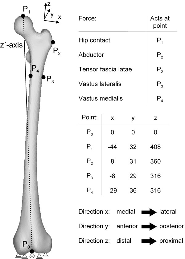
Figure 4.
Boundary conditions (constraints and force acting points) shown for the intact femur (taken from [20,27]). This figure shows the constraints used for the femur. In the distal condyle, the central node P0 was fixed using one thrust bearing, and four other nodes were constrained with floating bearings. Also, the acting node P1 of the hip contact force was constrained according to Speirs et al. [20] such that this node can only move along the z'-axis towards the centre of the distal condyle (P0). In addition, the used reduced muscle system with the acting points of the forces according to Heller et al. [27] is presented in this figure. It consists of abductors (M. gluteus minimus, M. gluteus maximus and M. gluteus medius), the M. tensor fascia latae, the M. vastus medialis and the M. vastus lateralis.

