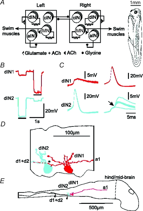
Figure 1. Xenopus tadpole, swimming CPG, and electrical coupling between dINs with their anatomy.
A, the tadpole swimming CPG comprises half-centres on each side of the spinal cord (squares). Each half-centre has populations of cINs, aINs, dINs and MNs (more details in text). Filled circle connections are inhibitory and triangles are excitatory. Connections onto a half-centre affect all neurons in it. Resistor symbols indicate electrical coupling between MNs and between dINs. The drawing (right) shows the tadpole at developmental stage 37/38. B–E, paired recording of two dINs filled by neurobiotin. B, when either dIN was hyperpolarised by square pulse current injection (bars, dIN1: −70 pA, dIN2: −100 pA), a smaller response was seen in the other neuron. C, the shape of spikes evoked at the start of a step current injection into one dIN and the responses in the other. dIN2 makes electrical synapse onto dIN1. In contrast, dIN2 displayed EPSPs (arrow) superimposed on the electrical synaptic response evoked by dIN1 firing. The EPSPs were consistent in latency but variable in size indicating a monosynaptic chemical connection. Five traces overlapped. D, high power tracing shows dIN1 has both ascending and descending axons (red, a1, d1) but dIN2 only has a descending axon (blue, d2). The descending axon of dIN1 may contact the dIN2 soma and basal dendrite (*). E, low power tracing shows somata and descending axons closely apposed to each other for a distance of about 200 μm (between arrowheads). Vertical dashed line indicates the hindbrain/midbrain border which is set as 0 in longitudinal position measurements.

