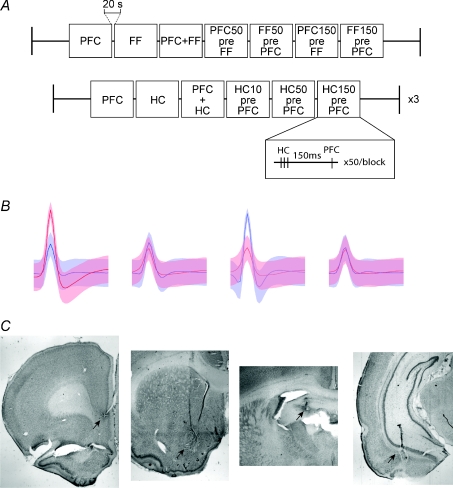
Figure 1. Stimulation protocols, example units, and electrode locations.
A, afferent areas of the nucleus accumbens were stimulated in blocks. The first protocol was tested under both awake and isoflurane conditions, while the second was repeated at three different stimulation amplitudes in the awake condition only. In the first protocol, either the fimbria-fornix (FF), the prefrontal cortex (PFC), both, or one followed by the other 50 or 150 ms apart, were stimulated. These were done in blocks of 50, with 5 s between stimuli and 20 s between blocks. In the second protocol, hippocampal CA1 (HC) or PFC were stimulated separately or simultaneously, or the HC was stimulated 10, 50 and 150 ms prior to the PFC. An example of one of the stimulations is inset, demonstrating the three HC stimulations (100 Hz) prior to the PFC stimulation with a 150 ms separation. B, an example of two cells recorded from the same tetrode, with each of four wires represented. The standard deviation of the waveform average is signified by the shaded areas. Each waveform is 1 ms in length. C, the locations of lesions from implanted stimulation and recording electrodes (arrows). From left to right: bipolar stimulating electrode at the border of the pre-and infra-limbic cortex, tetrode locations in the Nacb, bipolar stimulating electrode in the fimbria-fornix, and the ventral hippocampus (see Methods).

