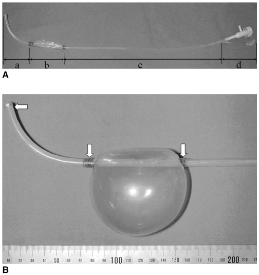
Fig. 1.
The new balloon sheath.
A. The deflated balloon sheath. (a) the distal angulated part, (b) the balloon part, (c) the straight part, and (d) the proximal handling part.
B. The inflated balloon sheath and the three gold markers (arrows) at each end of the balloon and at the tip of the balloon sheath.

