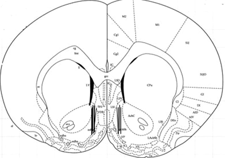
Figure 4.
Schematic representation of the microdialysis probe placements. The depicted section represents a coronal brain slice 1.6 mm anterior to bregma (Paxinos and Watson, 1998). Vertical bars correspond to the location of the active microdialysis membrane (2 mm) within the NAc shell. Cannulae for probe insertion were implanted in the right or left NAc shell of the rats in random order (n = 10).

