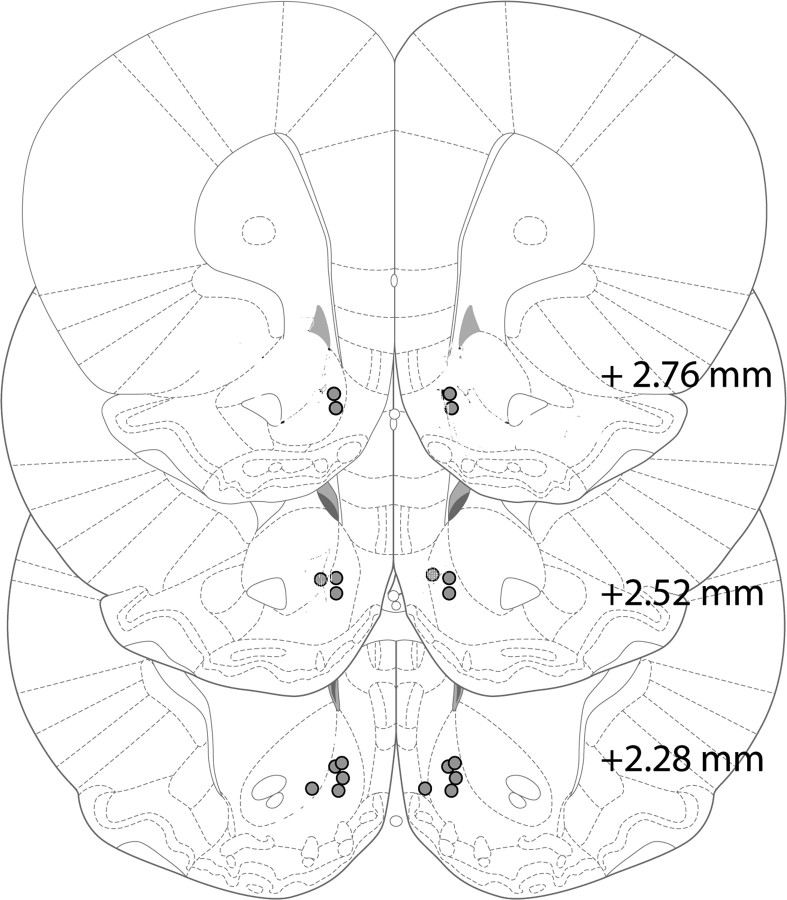
Figure 9.
Schematic representation of cannula implants for intra-NAc infusions. Placements of each drug microinjector in the NAc are depicted in the coronal sections. Each brain section represents a coronal slice 2.76, 2.52, or 2.28 mm anterior to bregma (Paxinos and Watson, 1998), and each circle corresponds to the location of the microinjector tip within the NAc (n = 10). Animals with cannula implants outside of the NAc were excluded from statistical analysis.

