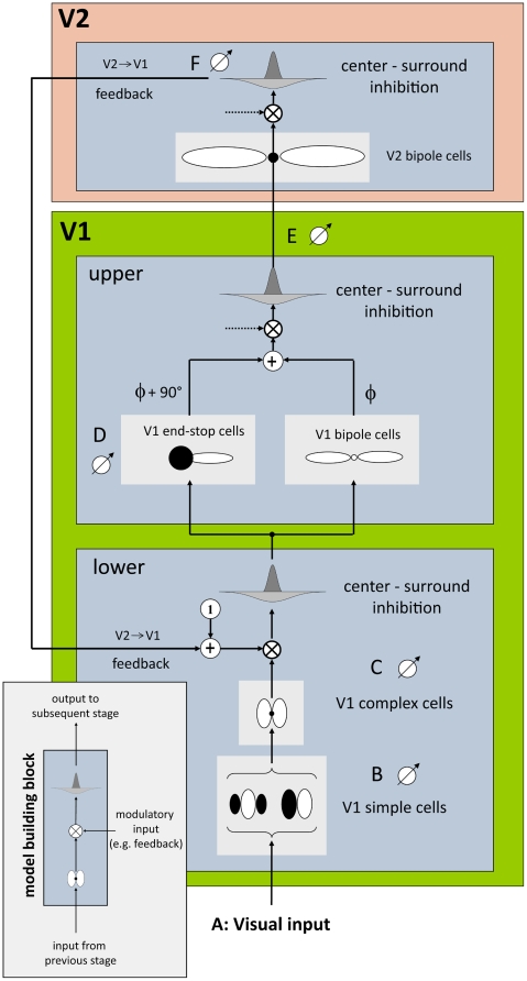
Figure 3. Our model simulates cells of two areas in the visual cortex, visual areas V1 and V2.
Each model (sub-) area is designed with respect to a basic building block scheme (bottom, left). The scheme consists of three subsequent steps, namely filtering, modulation and centre-surround inhibition. This scheme is applied three times in our model architecture (left), corresponding to upper and lower area V1 and area V2. In this model, modulatory input (provided by feedback from area V2) is only used in lower area V1. Otherwise the default modulatory input is set to 1 (which leaves the signal unchanged). The lower part of area V1 is modelled by simple and complex cells for initial contrast extraction. Note, that each cell pool consists of 12 oriented filters equally distributed between 0° and 180°. The upper part of V1 is modelled by end-stop and bipole cells which both receive input from lower V1. The additively combined signals are further passed to area V2 where long-range lateral connections are modelled by V2 bipole cells. Note, that “•” stands for a multiplicative connection of filter subfields as employed in V2 whereas “○” stands for an additive connection as employed in V1. Finally output of area V2 is used as feedback signal which closes the recurrent loop between areas V1 and V2.

