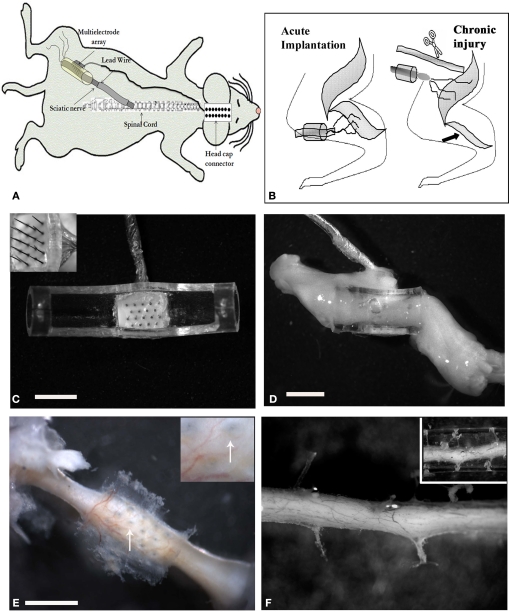
Figure 1.
Multi-electrode array nerve implants. (A) Illustration of the electrode array nerve guide and head cap connection. Schematic representation of the acute and chronic injury/implantation paradigm [(B) arrow indicates denervation induced atrophy of the normal target muscle]. (C) Top view of the 18 pin multi-electrode array mounted in a tubular nerve guide (top removed for clarity). The length of the electrodes varied from 0.5–0.9 mm, with the taller ones placed in the center of the array (insert). (D) Photograph of the regenerated nerve through the electrode-conduit assembly in an acute animal 3 weeks post-implantation. (E) Photograph showing the perforations left by the MEA in a chronic injured implanted animal (arrows in insert) and (F) through a collagen-filled tube. Scale bar = 2 mm (C), 5 mm (D) and 800 μm (E).

