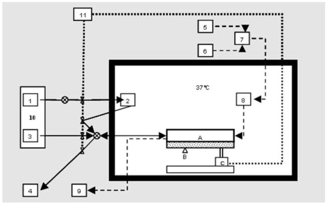
Figure 1.
Schematic representation of the Kerator bioreactor, showing A) Growth chamber, B) Camera, C) Tilting actuator, 1) Cold medium reservoir, 2) Warm medium reservoir, 3) Cell seeding and collection reservoir, 4) Waste, 5) CO2 supply, 6) Air supply, 7) Mass flow controller, 8) Humidifier bottle, 9) CO2 detector, 10) Peltier cooler, 11) Compressed air supply.

