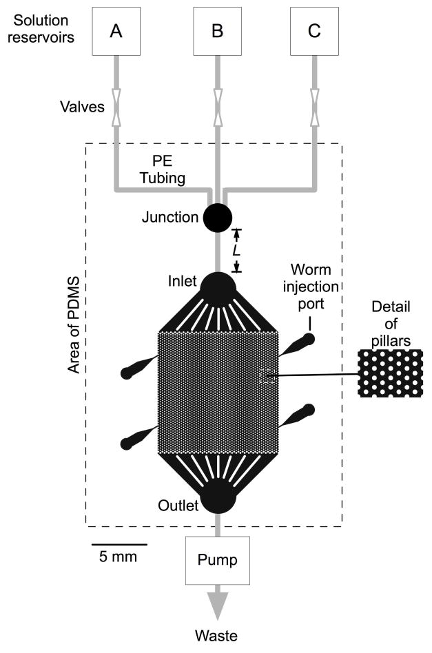
Figure 1.
Diagram of the artificial soil device. The broken line indicates the molded PDMS component. Within this region, the color black indicates spaces that are open to fluid flow. The worm is injected via one of four injection ports and crawls among microscopic posts in the central region, which measures 1 x 1 cm. The device is fed by three fluid reservoirs (A–C). Gray lines indicate polyethylene tubing. A piece of tubing of variable length L, inserted between the junction and the inlet, provides for an adjustable delay between switching the valves and the solution change experienced by the worm.

