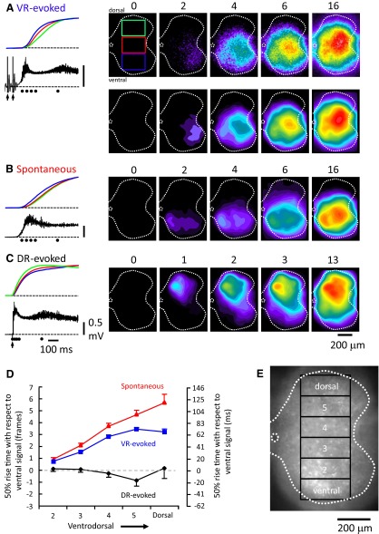
FIG. 10.
Visualization of the spread of optical activity during evoked and spontaneous bursts imaged from the cut transverse face of the rostral L5 segment. A–C: imaging of the fluo-3 AM labeled cord during VR-evoked (A), spontaneous (B), and DR-evoked (C) bursting in the presence of bicuculline (20 μM) and strychnine (5 μM). Each image is a difference image obtained by subtracting a preburst image (average of 5 frames) from the active frames. The top set of images was median filtered and the remaining were rank filtered. The numbers above the images indicate the frames (from stream acquisition performed at 1-ms interframe interval, 20 ms frame duration) selected for illustration. The panels to the left show the normalized optical signals from the ventral (blue), medial (red), and dorsal (green) areas of the cord (segment L5, right side) over a 33 frame period aligned with the electrical activity recorded from the ventral root (L5 in B and C and L4 in A). The last 2 stimuli of the train applied to the L5 ventral root (5 pulses, 20 Hz, 200 μs, 80 μA) are shown by the arrows under the electrical trace recorded from L4 ventral root. The arrow in C indicates the time of a single stimulus applied to L5 dorsal root (200 μs, 25 μA). The dots under the electrical traces indicate the timing of the frame shown on the right. Note in B that the spontaneous activity starts ventrally with the major activity ventromedial. D: graph summarizing the timing (in frames) of the fluorescent transients measured over 3 regions of interest shown in E. The 50% rise time of the optical signal is expressed with respect to the 50% signal rise time in the most ventral area. Data are averaged from 5 experiments and expressed as means ± SE.

