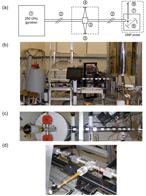
Figure 7.
(a) Schematic representation of the 250 GHz gyrotron, corrugated transmission system, and 380 MHz NMR probe. (1) 250 GHz gyrotron oscillator (2) Corrugated waveguide (22 mm i.d.). (3) Beam splitter; (4) Forward power detector; (5) Reflected power detector; (6) Focusing and reflecting mirror optics; (7) Helically corrugated waveguide (8 mm i.d.); and (8) Miter mirror.
(b) Photograph of the 250 GHz DNP experiment. The gyrotron magnet, on the left, is interfaced to a corrugated waveguide which leads to the NMR magnet, on the right. A touch-sensitive control interface is located midway on the waveguide support and alignment system.
(c) Composite photograph of the system illustrated schematically in Figure 7a (left) 250 GHz gyrotron the gyrotron tube is shown with vacion pumps in the gray superconducting magnet, (center) corrugated transmission system with the directional coupler visible in the center of the photograph, and (right) 380 MHz NMR magnet is visible on the edge of the photo. The NMR probe is not visible since it is under the magnet. The view in this photo is from above the gyrotron and waveguide looking down.
(d): Photograph of the 250 GHz quasi-optical directional coupler. Forward power is coupled to the detector diode by means of a short dielectric taper, dielectric horn, and a circular-to-rectangular transition. An attenuator allows the power to be adjusted to the linear range of the diode. The detection circuit has been designed with high loss to avoid reflections across the beam splitter.

