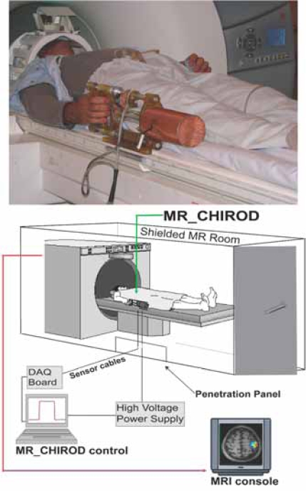
Fig. (1).
Arrangement of the MR compatible, hand-induced, robotic device (MR_CHIROD) in the MRI suite. A, top: MR_CHIROD used in the scanner; it is attached to the scanner while the subject, lying in the magnet operates it. B, bottom: Schematic of the MR_CHIROD set up in the MRI suite. The resistive element (ERF damper) consists of two electrodes and contains the ERF. The piston (piston shaft drawn) moves through the ERF with a controlled force of contraction provided by the voltage-controlled variable viscosity of the ERF fluid. A Faraday cage encloses the core of the device, allowing a necessary opening for the movable piston shaft. The negative electrode of the damper (connecting to the negative terminal of the power supply) and the Faraday cage are grounded to the penetration panel of the MR room. A low-pass filter is attached to the penetration panel. Sensor readings (force, position) are transmitted through the penetration panel through grounded DSub-9 connectors. The sensor wires are coaxially shielded and all are properly grounded to the penetration panel. The sensor readings are used for real-time, closed loop control of the ERF resistive element. The output from the control-loop regulates the voltage output of the power supply, in turn ensuring control of the ERF resistive element and the generated resistive force.

