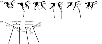
Figure 2.
(a) A sketch of the key points of the equine transverse gallop. The near side (right side of the horse) forelimb and hindlimb are indicated in black and the far side (left side of the horse) in white. Beginning with the aerial phase of the gait (the collected phase) at left, the animal lands on its right hindlimb and progresses through from rear to front alternating right and left sides. The animal eventually takes off from the final (lead) forelimb. The net impulse applied by each limb is indicated by the black vector arrow (horse image after Gray (1953), impulse vector calculated from Merkens et al. (1993)). The initial hindlimb contact results in a net acceleration because the CoM is located forward of the contact, while the final forelimb contact results in a net deceleration because the CoM lies behind the contact. (b) In order to clarify the mechanics of the transition, the horse is modelled as a point mass attached to a massless limb strut. The CoM velocity vector (grey vector arrow) is progressively deflected by the impulse (black vector arrow) that is transmitted through the limb strut at each footfall. The angle of the massless limb strut determines the direction of the impulse vector and, consequently, the direction in which momentum is lost. The CoM velocity vector undergoes a total angular deflection of α as it transitions from downward–forward to upward–forward. But, by dividing α into four equal parts (an idealization of the distribution used by horses) the energy lost in the transition is reduced from that lost in a single collision by a factor of four (Ruina et al. 2005).

