
Figure 1.
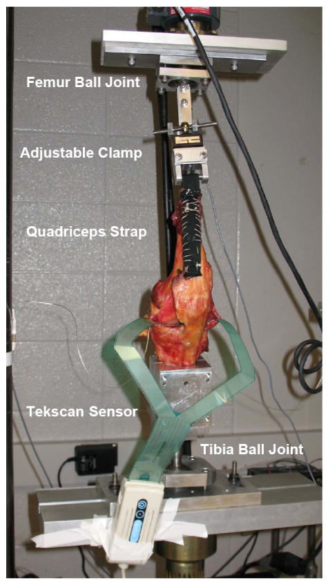
Experimental test set-up for axial loading condition. Knees were mounted on an MTS machine with Tekscan pressure sensors inserted into the medial and lateral plateaus of the knee joint distal to the meniscus. The soft tissue was removed to expose the quadriceps tendon, the joint space, and the collateral ligaments. A nylon strap was sutured to the quadriceps tendon, a steel rod was fixed in the femur and the tibia was potted in a cylindrical bone cement mold. Each specimen was attached to a testing fixture on a material testing machine (Model 312, MTS Systems Corp., Eden Prairie, MN). The tibia and femur were mounted on ball joints to allow natural 6 DOF loading patterns.