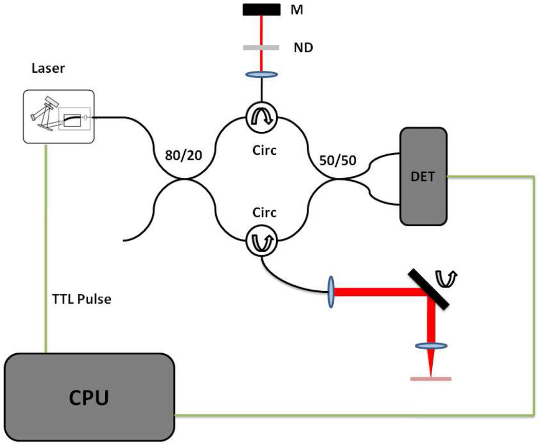
Fig. 2.
OFDI Imaging setup. The output from the swept laser is directed through an 80/20 splitter into reference and sample arms. Each arm contains a circulator and signal reflection elements. The reference arm consists of a neutral density filter and a fixed mirror (M). The sample arm contains a two-axis galvanometer scanning system. The dual balanced detector (DET) output into a computer (CPU) for digitization and processing. The resonant scanner TTL pulse is used for acquisition triggering.

