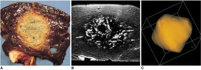
Fig. 7.
A six-ablation zone designed with four spheres in the x-y plane and two along the z-axis, with ablation spheres which overlap by 23% of their diameter.
A. Photograph of longitudinal section of the oval-shaped specimen depicts an ablation zone.
B. T2-weighted FSE (TR 5067/TE 102) coronal image shows a low-signal zone (arrows).
C. Three-dimensional ablation zone reconstructed from MR images appears as a composite zone (irregularly contoured sphere), with no definite pits at the junction of the three small spheres.

