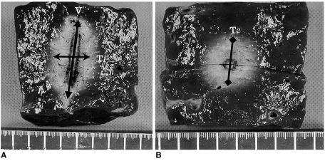
Fig. 2.
Measurement of the ablated area. Photographs of specimen created by dry RF ablation (group A) in the electrode insertion axis (A) and in the transverse axis perpendicular to the electrode shaft (B). Arrows indicate the three directional diameters of the RF-induced coagulation necrosis: V indicates the vertical diameter; T1, the transverse diameter on the plane along the electrode insertion axis; and T2, the transverse diameter on the plane perpendicular to the electrode shaft.

