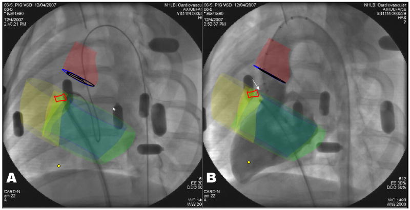
Figure 4. XFM positioning of delivery sheath and VSD occluder deployment.
A: Antegrade sheath delivery guided by XFM. The sheath is directed toward the left ventricular apex using a flexible guidewire. The XFM roadmap includes right (yellow) and left (blue) ventricular endocardial contours, left ventricular epicardial contour (green), aortic annulus (blue), aortic root (red), and VSD tract (bright red).
B: Confirmatory XFM radiocontrast ventriculography before release of VSD occluder device deployed in position. Features include the VSD occluder (white arrow), VSD tract (bright red contour), right (yellow) and left (blue) ventricular endocardial and left ventricular epicardial (green) contours, aortic valve (dark blue) and aortic root (dark red).

