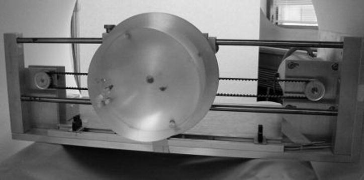
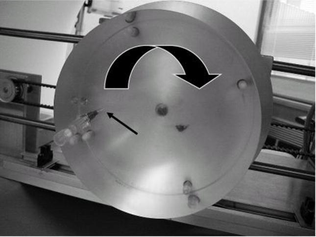
Figure 3.
(a) Photograph of the motion apparatus within the gantry of the CT system and a close-up of the phantom (b). The 22 gauge hypodermic needle inserted into the 15 cm acrylic cylinder is indicated by the narrow black arrow. The large arrow indicates the direction of rotation. The screws that mount the acrylic phantom to the metal plate of the motion apparatus are visible through the clear acrylic. Using a computer-controlled stepping motor, the phantom was rotated at 3 rotations per second to match the rotation time of the gantry. (c) A CT image of the static phantom demonstrates the appearance of the metal needle.


