FIG. 2.

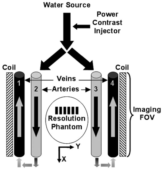
Schematic of the flow phantom. Arrows define directional flow within the tubes, and arteries (tubes 2 and 3) and veins (tubes 1 and 4) are labeled. Note the static resolution phantom, and placement of surface coils along the L/R Y-axis.

Schematic of the flow phantom. Arrows define directional flow within the tubes, and arteries (tubes 2 and 3) and veins (tubes 1 and 4) are labeled. Note the static resolution phantom, and placement of surface coils along the L/R Y-axis.