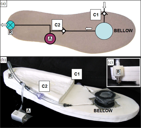
Figure 2.

PhAFO pneumatic circuit diagram and shoe sole. Pneumatic circuit diagram (a) and actual foam sole (b) with bellow pump mounted at the metatarsal. (C1) check valve is open to atmosphere for intake, (C2) check valve ensures one-way flow direction from bellow to actuator, (A) actuator for locking mechanism, and (R) pressure release valve for exhaust. Valve (R) opens to atmosphere upon contact with the floor (c).
