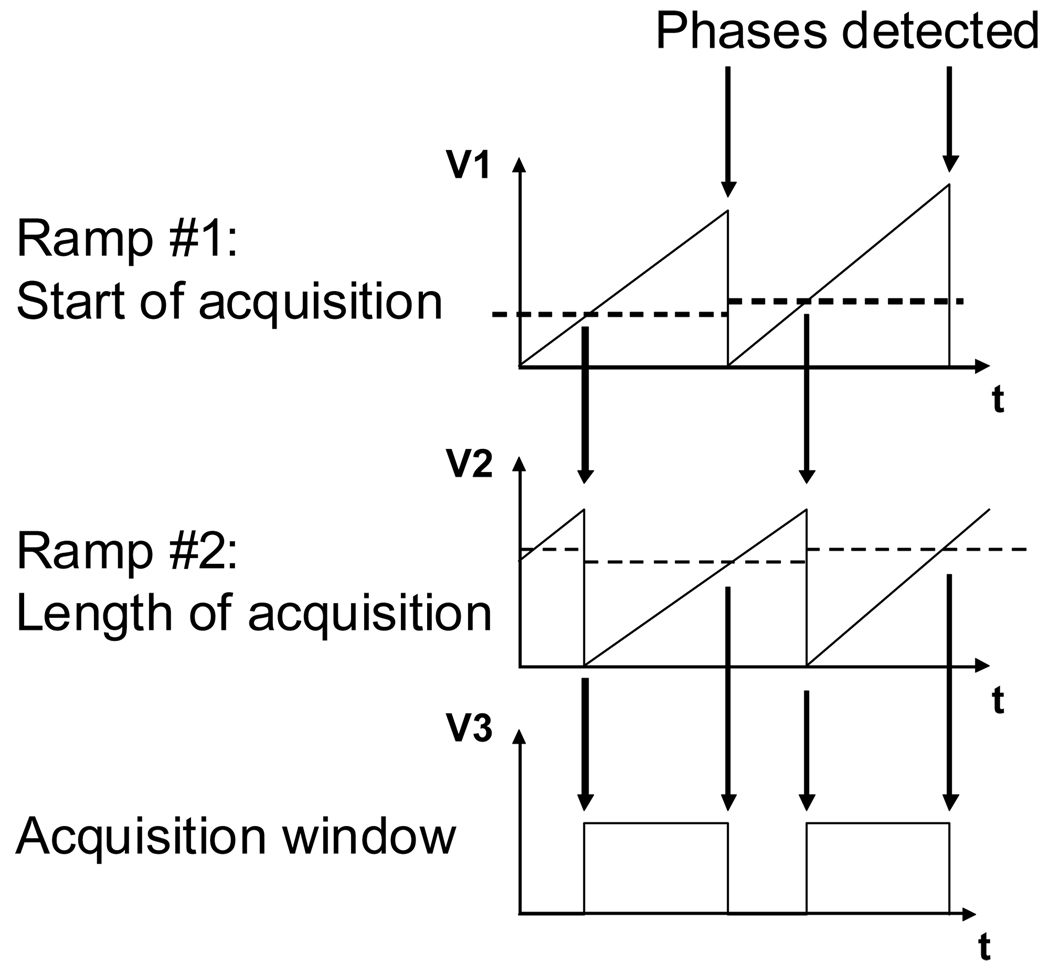
Figure 3. TIMING.
Two time-voltage ramps are necessary for placing the acquisition window at anytime compare to the incoming signal. Ramp #1 is reset when the phase is detected and compare to a first reference timing. When ramp #1 passes the reference voltage, acquisition is started and ramp # 2 is reset. Finally ramp #2 is compared to a second reference voltage. Put together, these two ramps allow for defining an acquisition window of any length and at any time.

