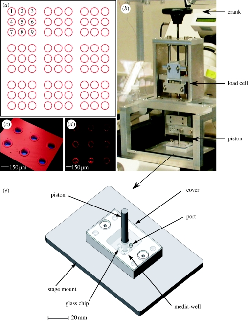
Figure 1.
Images depicting (a) the layout of the microwell arrays etched into one borosilicate chip, (b) the actuator system, (c) an optical profilometer image showing the etched microwells with the lips clearly visible, (d) a laser scanning microscope (LSM) image of a microwell array showing the microsphere ring under excitation and (e) the living cell array (LCA). The LCA uses an aluminium plate to provide the support for a rigid quartz window. The quartz window was selected to provide adequate support to prevent the borosilicate chips from cracking under the load. (b) The actuator system acts as a manual linear actuator for the pistons. This system is advantageous since it removes instabilities and provides coaxial alignment of the piston to the borosilicate chip.

