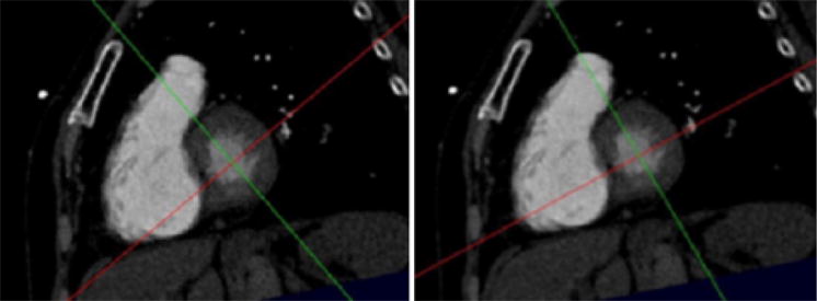
Fig. 6.

Short-axis view at the base of the heart. Scrolling the images in this plane will give the short axis stack to be used to calculate left ventricular volumes. The left hand image shows the orientation of the cross hairs at the end of Step 3, namely after the creation of the short axis stack. As noted in the description of Step 4, a 4-chamber view aligned along the plane defined by the red line will not demonstrate the maximum diameter of the right ventricle. In the right hand image (Step 4) the red line has been turned so that the 4-chamber plane it defines includes the full extent of the right ventricle.
