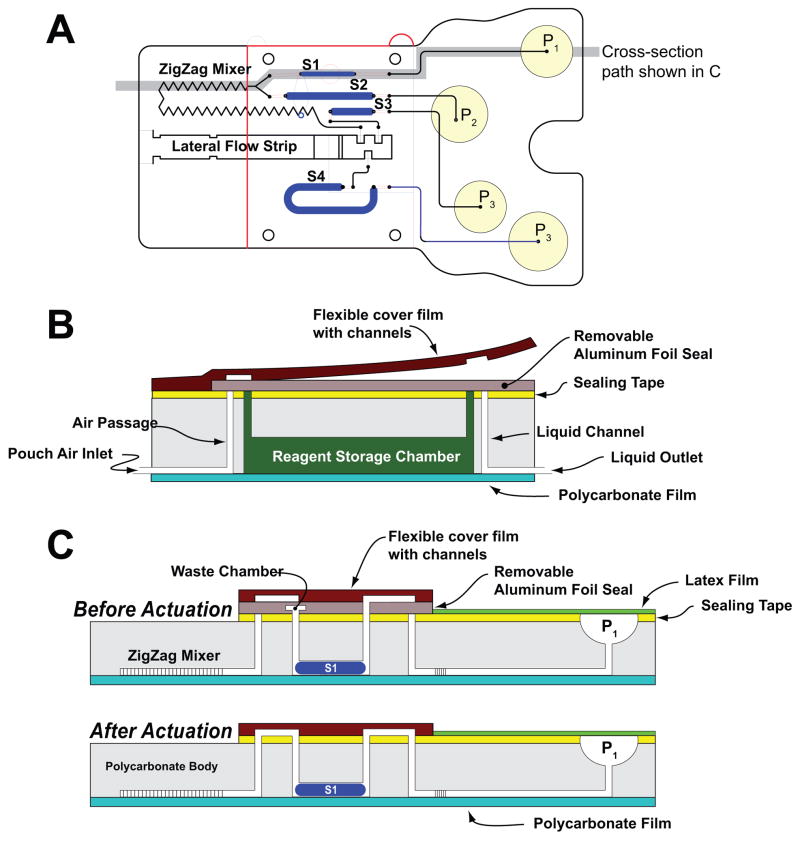
Fig. 1.
A schematic depiction of the polycarbonate fluidic chip consisting of air pouches (P1–P4), a metering chamber (S1), reagents storage chambers (S2–S4), a zigzag mixer, and a lateral flow (LF) strip. (A) top view; (B) cross-section along the width of the cassette in its storage (pre-activation) state; (C) cross-sections along the length of the cassette prior (top) and after (bottom) the cassette activation.

