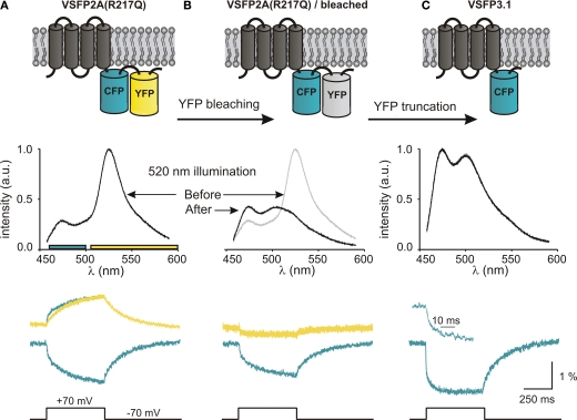
Figure 5.
Development of third generation voltage-sensitive fluorescent proteins. The membrane topology of VSFP2A(R217Q) (A), VSFP2A(R217Q) after acceptor photobleaching (B) and VSFP3.1 (C) is illustrated in top panels. Emission spectra recorded for each constructs using 440-nm excitation light are shown below. The lower panel shows the depolarization-induced fluorescence signals recorded in the yellow and cyan channels. For VSFP2A(R217Q), a scaled mirror image of the cyan signal is shown aligned with the yellow signal; note the fast CFP component. For VSFP3.1, the top trace represents the onset of the fluorescence signal at a magnified time scale (from Lundby et al., 2008).

