Fig. 2.

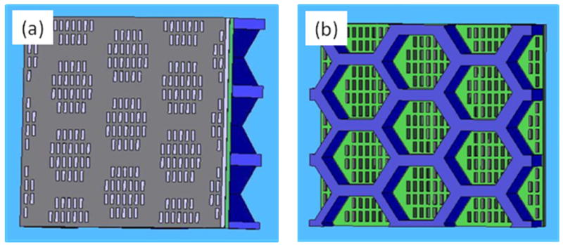
Schematics of magnetic sifter structure. (a) The magnetic layer containing slots (top view). (b) The silicon skeleton and exposed nitride membrane containing slots (bottom view). Film thicknesses are not drawn to scale.

Schematics of magnetic sifter structure. (a) The magnetic layer containing slots (top view). (b) The silicon skeleton and exposed nitride membrane containing slots (bottom view). Film thicknesses are not drawn to scale.