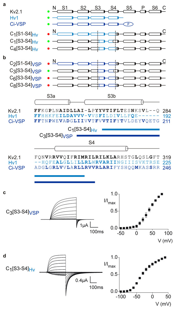
Figure 4. Transfer of the voltage-sensor paddle motif from Hv1 or Ci-VSP into Kv2.1 channels.
Overview of chimeras between Hv1 (a, light blue), Ci-VSP (b, dark blue) and Kv2.1 (black). Constructs that result in functional Kv channel activity when expressed in oocytes are indicated with green circles and those that are non-functional are indicated with red circles. Dashed lines are the same as in Fig 1. The amino acid alignment shows the sequence of Kv2.1, Hv1 and Ci-VSP in S3 through S4, highlighting (blue bars) the stretch of residues transferred to form the two chimeras indicated. c, Current traces and tail current voltage-activation relations (n = 3; error bars are S.E.M.) for a chimera expressed in oocytes where the paddle of Ci-VSP was transferred into Kv2.1. Test depolarizations were to voltages between −50 and +80 mV, holding voltage was −80 mV and tail voltage was −50 mV. d, Current traces and tail current voltage-activation relations (n = 3; error bars are S.E.M.) for a chimera where the paddle of Hv1 was transferred into Kv2.1. Test depolarizations were to voltages between −100 and +40 mV, holding voltage was −90 mV and tail voltage was −90 mV.

